


AMD Geode™ SC2200 Processor Data Book 241
Core Logic Module - Bridge, GPIO, and LPC Registers - Function 0
32580B
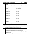
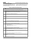
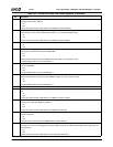
Offset 18h-1Bh LAD_D1 — LPC Address Decode 1 Register (R/W) Reset Value: 00000000h
31:16 Reserved. Must be set to 0.
15:9 Wide Generic Base Address Select. Defines a 512 byte space. Can be mapped anywhere in the 64 KB I/O space. AC97
and other configuration registers are expected to be mapped to this range. It is wide enough to allow many unforeseen
devices to be supported. Enabled at F0BAR1+I/O Offset 10h[9].
Note: The selected range must not overlap any address range that is positively decoded by F0BAR1+I/O Offset 10h bits
[17], [14:10], and [8:0].
8:0 Reserved. Must be set to 0.
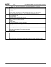
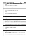
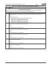
Offset 1Ch-1Fh LPC_ERR_SMI — LPC Error SMI Register (R/W) Reset Value: 00000080h
31:12 Reserved. Must be set to 0.
11 LPCPD# Override Enable. Determines how LPCPD# output is controlled.
0: ACPI logic.
1: LPCPD# Override Value bit (bit 10 of this register).
10 LPCPD# Override Value. Selects value of LPCPD# output if bit 11 of this register is set to 1.
0: Power down sequence.
1: Normal power.
9 SMI Serial IRQ Enable. Allows serial IRQ to generate an SMI.
0: Disable.
1: Enable.
Top Level SMI status is reported at F1BAR0+I/O Offset 02h[3].
Second level status is reported at bit 6 of this register.
8 SMI Configuration for LPC Error Enable. Allows LPC errors to generate an SMI.
0: Disable.
1: Enable.
Top Level SMI status is reported at F1BAR0+I/O Offset 02h[3].
Second level status is reported at bit 5 of this register.
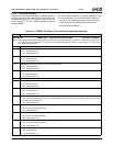
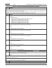
7 LPCPD# Pin Status. (Read Only) Reflects the current value of the LPCPD# output signal.
6 SMI Source is Serial IRQ. Indicates whether or not an SMI was generated by an SERIRQ.
0: No.
1: Yes.
Write 1 to clear.
To enable SMI generation, set bit 9 of this register to 1.
This is the second level of status reporting. The top level status is reported in F1BAR0+I/O Offset 02h[3].
Writing a 1 to this bit also clears the top level status bit as long as bit 5 of this register is cleared.
5 LPC Error Status. Indicates whether or not an SMI was generated by an error that occurred on LPC.
0: No.
1: Yes.
Write 1 to clear.
To enable SMI generation, set bit 8 of this register to 1.
This is the second level of status reporting. The top level status is reported in F1BAR0+I/O Offset 02h[3].
Writing a 1 to this bit also clears the top level status bit as long as bit 6 of this register is cleared.
4 LPC Multiple Errors Status. Indicates whether or not multiple errors have occurred on LPC.
0: No.
1: Yes.
Write 1 to clear.
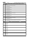
Table 6-31. F0BAR1+I/O Offset: LPC Interface Configuration Registers (Continued)
Bit Description