


58 AMD Geode™ SC2200 Processor Data Book
Signal Definitions
32580B
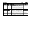
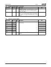
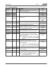
PAR J4 I/O Parity. Parity generation is required by all PCI agents.
The master drives PAR for address- and write-data
phases. The target drives PAR for read-data phases. Par-
ity is even across AD[31:0] and C/BE[3:0]#.
For address phases, PAR is stable and valid one PCI
clock after the address phase. It has the same timing as
AD[31:0] but is delayed by one PCI clock.
For data phases, PAR is stable and valid one PCI clock
after either IRDY# is asserted on a write transaction or
after TRDY# is asserted on a read transaction.
Once PAR is valid, it remains valid until one PCI clock
after the completion of the data phase. (Also see
PERR#.)
D12
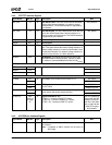
FRAME# D8 I/O Frame Cycle. Frame is driven by the current master to
indicate the beginning and duration of an access.
FRAME# is asserted to indicate the beginning of a bus
transaction. While FRAME# is asserted, data transfers
continue. FRAME# is de-asserted when the transaction
is in the final data phase.
This signal is internally connected to a pull-up resistor.
---
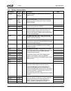
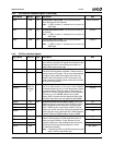
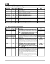
IRDY# F2 I/O Initiator Ready. IRDY# is asserted to indicate that the
bus master is able to complete the current data phase of
the transaction. IRDY# is used in conjunction with
TRDY#. A data phase is completed on any PCI clock in
which both IRDY# and TRDY# are sampled as asserted.
During a write, IRDY# indicates that valid data is present
on AD[31:0]. During a read, it indicates that the master is
prepared to accept data. Wait cycles are inserted until
both IRDY# and TRDY# are asserted together.
This signal is internally connected to a pull-up resistor.
D14
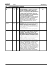
TRDY# F1 I/O Target Ready. TRDY# is asserted to indicate that the tar-
get agent is able to complete the current data phase of
the transaction. TRDY# is used in conjunction with
IRDY#. A data phase is complete on any PCI clock in
which both TRDY# and IRDY# are sampled as asserted.
During a read, TRDY# indicates that valid data is present
on AD[31:0]. During a write, it indicates that the target is
prepared to accept data. Wait cycles are inserted until
both IRDY# and TRDY# are asserted together.
This signal is internally connected to a pull-up resistor.
D13
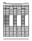
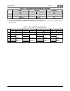
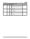
3.4.6 PCI Bus Interface Signals (Continued)
Signal Name BalL No. Type Description Mux