


250 AMD Geode™ SC2200 Processor Data Book
Core Logic Module - SMI Status and ACPI Registers - Function 1
32580B
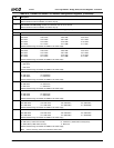
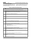
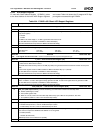
Offset 06h-07h Second Level General Traps & Timers Status Register (RC) Reset Value: 0000h
The bits in this register contain second level of status reporting. Top level status is reported in F1BAR0+I/O Offset 00h/02h[9]. Reading
this register clears the status at both the second and top levels.
A read-only “Mirror” version of this register exists at F1BAR0+I/O Offset 04h. If the value of this register must be read without clearing
the SMI source (and consequently de-asserting SMI), F1BAR0+I/O Offset 04h can be read instead.
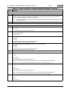
15:6 Reserved.
5 PCI/ISA Function Trap. Indicates whether or not an SMI was caused by a trapped PCI/ISA configuration cycle
0: No.1:Yes.
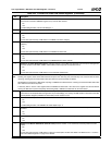
To enable SMI generation for:
— Trapped access to ISA Legacy I/O register space set F0 Index 41h[0] = 1.
— Trapped access to F1 register space set F0 Index 41h[1] = 1.
— Trapped access to F2 register space set F0 Index 41h[2] = 1.
— Trapped access to F3 register space set F0 Index 41h[3] = 1.
— Trapped access to F4 register space set F0 Index 41h[4] = 1.
— Trapped access to F5 register space set F0 Index 41h[5] = 1.
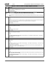
4 SMI Source is Trapped Access to User Defined Device 3 (UDEF3). Indicates whether or not an SMI was caused by a
trapped I/O or memory access to User Defined Device 3 (F0 Index C8h).
0: No.
1: Yes.
To enable SMI generation, set F0 Index 82h[6] = 1.
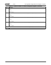
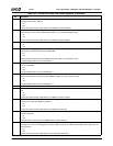
3 SMI Source is Trapped Access to User Defined Device 2 (UDEF2). Indicates whether or not an SMI was caused by a
trapped I/O or memory access to User Defined Device 2 (F0 Index C4h).
0: No.
1: Yes.
To enable SMI generation, set F0 Index 82h[5] = 1.
2 SMI Source is Trapped Access to User Defined Device 1 (UDEF1). Indicates whether or not an SMI was caused by a
trapped I/O or memory access to User Defined Device 1 (F0 Index C0h).
0: No.
1: Yes.
To enable SMI generation, set F0 Index 82h[4] = 1.
1 SMI Source is Expired General Purpose Timer 2. Indicates whether or not an SMI was caused by the expiration of Gen-
eral Purpose Timer 2 (F0 Index 8Ah).
0: No.
1: Yes.
To enable SMI generation, set F0 Index 83h[1] = 1.
0 SMI Source is Expired General Purpose Timer 1. Indicates whether or not an SMI was caused by the expiration of Gen-
eral Purpose Timer 1 (F0 Index 88h).
0: No.
1: Yes.
To enable SMI generation, set F0 Index 83h[0] = 1.
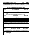
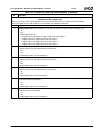
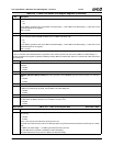
Offset 08h-09h SMI Speedup Disable Register (Read to Enable) Reset Value: 0000h
15:0 SMI Speedup Disable. If bit 1 in the Suspend Configuration Register is set (F0 Index 96h[1] = 1), a read of this register
invokes the SMI handler to re-enable Suspend Modulation.
The data read from this register can be ignored. If the Suspend Modulation feature is disabled, reading this I/O location has
no effect.
Offset 0Ah-1Bh Reserved Reset Value: 00h
These addresses should not be written.
Offset 1Ch-1Fh ACPI Timer Register (RO) Reset Value: xxxxxxxxh
Note: This register can also be read at F1BAR1+I/O Offset 1Ch.
31:24 Reserved.
23:0 TMR_VAL. This field returns the running count of the power management timer.
Table 6-33. F1BAR0+I/O Offset: SMI Status Registers (Continued)
Bit Description