


348 AMD Geode™ SC2200 Processor Data Book
Video Processor Module - Video Processor Registers - Function 4
32580B
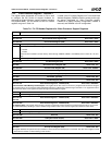
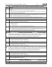
19:16 CLK_SEL (Clock Select). Selects frequency (in MHz) of the display clock.
0000: 25.175 0100: 50 1000: 65 1100: 108
0001: 31.5 0101: 49.5 1001: 75 1101: 135
0010: 36 0110: 56.25 1010: 78.5 1110: 27
0011: 40 0111: 44.9 1011: 94.5 1111: 24.923052
15 LFTC (Loop Filter Time Constant). This bit should be set when m (bits [14:8]) value is higher than 30.
14:8 m (Defines m PLL2 Value). Relevant when SEL_REG_CAL (bit 20) = 1. The following formula is used for calculating the
frequency using m and n values:
Fvco = OSCCLK * Km/Kn
Km = m + 1
Kn = n + 1
OSCCLK = 27 MHz
7:4 Reserved.
3:0 n (Defines n PLL2 Value). Relevant when SEL_REG_CAL (bit 20) = 1. The following formula is used for calculating the fre-
quency using m and n values:
Fvco = OSCCLK * Km/Kn
Km = m + 1
Kn = n + 1
OSCCL = 27 MHz
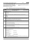
Offset 30h-33h Reserved Reset Value: 00000000h
Offset 34h-37h Reserved Reset Value: 00000000h
Offset 38h-3Bh Reserved Reset Value: 00000000h
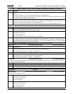
Offset 3Ch-3Fh Video Downscaler Control Register (R/W) Reset Value: 00000000h
Controls the characteristics of the integrated video downscaler.
31:7 Reserved.
6 DTS (Downscale Type Select).
0: Type A (Downscale formula is 1/m+1, m pixels are dropped, 1 pixel is kept).
1: Type B (Downscale formula is m/m+1, m pixels are kept, 1 pixel is dropped).
5 Reserved.
4:1 DFS (Downscale Factor Select). Determines the downscale factor to be programmed into these bits, where m is used to
derive the desired downscale factor depending on bit 6 (DTS).
0 DCF (Downscaler and Filtering). Enables/disables downscaler and filtering logic.
0: Disable.
1: Enable.
Note: No downscaling support for RGB 5:6:5 and YUV 4:2:0 video formats.
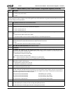
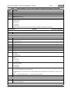
Offset 40h-43h Video Downscaler Coefficient Register (R/W) Reset Value: 00000000h
Indicates filter coefficients. The filters can be programmed independently to increase video quality when the downscaler is implemented.
Valid values for each filter coefficient are 0-15. The sum of coefficients must be 16. FLT_CO_4 is used with the earliest pixels and
FLT_CO_1 is used with the latest. Only luminance values of pixels are filtered.
31:28 Reserved.
27:24 FLT_CO_4 (Filter Coefficient 4). For the tap-4 filter.
23:20 Reserved.
19:16 FLT_CO_3 (Filter Coefficient 3). For the tap-3 filter.
15:12 Reserved.
11:8 FLT_CO_2 (Filter Coefficient 2). For the tap-2 filter.
7:4 Reserved.
3:0 FLT_CO_1 (Filter Coefficient 1). For the tap-1 filter.
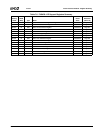
Table 7-7. F4BAR0+Memory Offset: Video Processor Configuration Registers (Continued)
Bit Description