


AMD Geode™ SC2200 Processor Data Book 421
Electrical Specifications
32580B
t
USB_DJU22
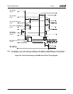
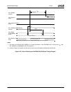
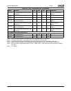
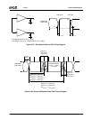
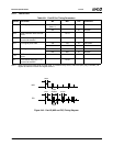
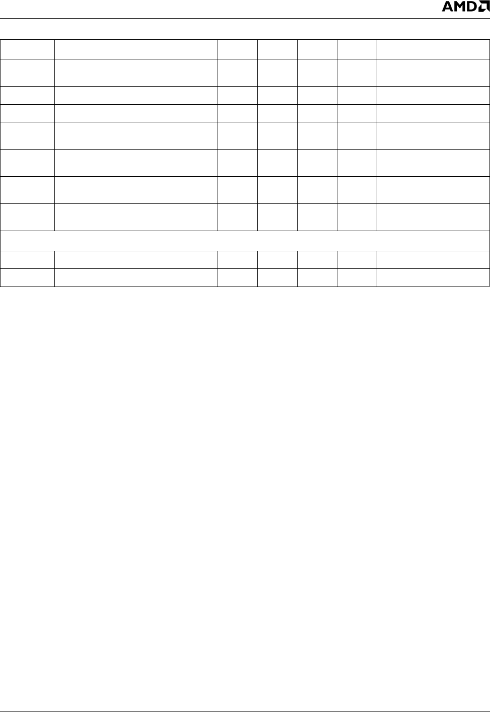
Source differential driver jitter for paired
transactions
–150 150 ns 9-38 Function (downstream),
Note 4
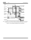
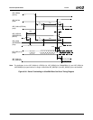
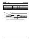
t
USB_SE2
Source EOP width 1.25 1.5 μs 9-39 Note 4, Note 5
t
USB_DE2
Differential to EOP transition skew –40 100 ns 9-39 Note 5
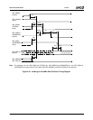
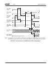
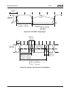
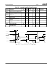
t
USB_RJD21
Receiver data jitter tolerance for con-
secutive transactions
–152 152 ns 9-40 Host (upstream),
Note 4
t
USB_RJD22
Receiver data jitter tolerance for paired
transactions
–200 200 ns 9-40 Host (upstream),
Note 4
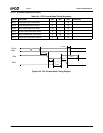
t
USB_RJU21
Receiver data jitter tolerance for con-
secutive transactions
–75 75 ns 9-40 Function (downstream),
Note 4
t
USB_RJU22
Receiver data jitter tolerance for paired
transactions
–45 45 ns 9-40 Function (downstream),
Note 4
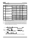
Low Speed Receiver EOP Width (Note 5)
t
USB_RE21
Must reject as EOP 330 ns 9-38
t
USB_RE22
Must accept as EOP 675 ns 9-38
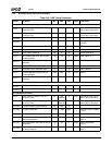
Note 1. Unless otherwise specified, all timings use a 50 pF capacitive load (C
L
) to ground.
Note 2. Full-speed timing has a 1.5 KΩ pull-up to 2.8 V on the DPOS_Port1,2,3 lines.
Note 3. Timing difference between the differential data signals (DPOS_PORT1,2,3 and DNEG_PORT1,2,3).
Note 4. Measured at the crossover point of differential data signals (DPOS_PORT1,2,3 and DNEG_PORT1,2,3).
Note 5. EOP is the End of Packet where DPOS_PORT
t
= DNEG_PORT = SE0. SE0 occurs when output level voltage ≤
V
SE
(Min).
Note 6. C
L
= 350 pF.
Table 9-29. USB Timing Parameters (Continued)
Symbol Parameter Min Max Unit Figure Comments