256 AMD Geode™ SC2200 Processor Data Book
Core Logic Module - SMI Status and ACPI Registers - Function 1
32580B
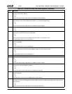
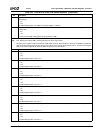
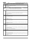
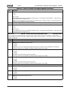
0 PWRBTN_DBNC_DIS (Power Button Debounce). When enabled, a high-to-low or low-to-high transition of greater than
15.8 ms is required on PWRBTN# before it is recognized.
0: Enable. (Default)
1: Disable. (No debounce)
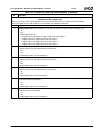
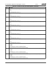
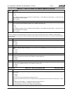
Offset 08h-09h PM1A_STS — PM1A Top Level PME/SCI Status Register (R/W) Reset Value: 0000h
Notes: 1. This is the top level of PME/SCI status reporting for these events. There is no second level.
2. If SCI generation is not desired, the status bits are still set by the described conditions and can be used for monitoring pur-
poses.
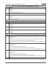
15 WAK_STS (Wakeup Status). Indicates whether or not an SCI was caused by the occurrence of an enabled wakeup event.
0: No.
1: Yes.
This bit is set when the system is in any Sleep state and an enabled wakeup event occurs (wakeup events are configured at
F1BAR1+I/O Offset 0Ah and 12h). After this bit is set, the system transitions to a Working state.
SCI generation is always enabled.
Write 1 to clear.
14:12 Reserved. Must be set to 0.
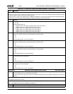
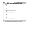
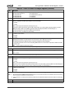
11 PWRBTNOR_STS (Power Button Override Status). Indicates whether or not an SCI was caused by the power button
being active for greater than 4 seconds.
0: No.
1: Yes.
SCI generation is always enabled.
Write 1 to clear.
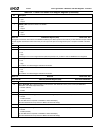
10 RTC_STS (Real-Time Clock Status). Indicates if a Power Management Event (PME) was caused by the RTC generating
an alarm (RTC IRQ signal is asserted).
0: No.
1: Yes.
For the PME to generate an SCI, set F1BAR1+I/O Offset 0Ah[10] to 1 and F1BAR1+I/O Offset 0Ch[0] to 1. (See Note 2 in
the general description of this register.)
Write 1 to clear.
9 Reserved. Must be set to 0.
8 PWRBTN_STS (Power Button Status). Indicates if PME was caused by the PWRBTN# going low while the system is in a
Working state.
0: No.
1: Yes.
For the PME to generate an SCI, set F1BAR1+I/O Offset 0Ah[8] = 1 and F1BAR1+I/O Offset 0Ch[0] = 1. (See Note 2 in the
general description of this register.)
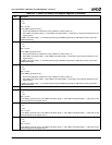
In a Sleep state or the Soft-Off state, a wakeup event is generated when the power button is pressed (regardless of the
PWRBTN_EN bit, F1BAR1+I/O Offset 0Ah[8], setting).
Write 1 to clear.
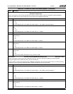
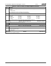
7:6 Reserved. Must be set to 0.
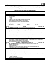
5 GBL_STS (Global Lock Status). Indicates if PME was caused by the BIOS releasing control of the global lock.
0: No.
1: Yes.
This bit is used by the BIOS to generate an SCI. BIOS writes the BIOS_RLS bit (F1BAR1+I/O Offset 0Fh[1]) which in turns
sets the GBL_STS bit and raises a PME.
For the PME to generate an SCI, set F1BAR1+I/O Offset 0Ah[5] to 1 and F1BAR1+I/O Offset 0Ch[0] to 1. (See Note 2 in the
general description of this register.)
Write 1 to clear.
Table 6-34. F1BAR1+I/O Offset: ACPI Support Registers (Continued)
Bit Description


