


AMD Geode™ SC2200 Processor Data Book 247
Core Logic Module - SMI Status and ACPI Registers - Function 1
32580B
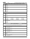
5 SMI Source is Video Retrace. Indicates whether or not an SMI was caused by a video retrace event as decoded from the
internal serial connection (PSERIAL register, bit 7) from the GX1 module.
0: No.
1: Yes.
To enable SMI generation, set F0 Index 83h[2] to 1.
4 Reserved. Reads as 0.
3 SMI Source is LPC. Indicates whether or not an SMI was caused by the LPC interface.
0: No.
1: Yes.
The next level (second level) of SMI status is at F0BAR1+I/O Offset 1Ch[6:5].
2 SMI Source is ACPI. Indicates whether or not an SMI was caused by an access (read or write) to one of the ACPI registers
(F1BAR1).
0: No.
1: Yes.
The next level (second level) of SMI status is at F1BAR0+I/O Offset 20h.
1 SMI Source is Audio Subsystem. Indicates whether or not an SMI was caused by the audio subsystem.
0: No.
1: Yes.
The next level (second level) of SMI status is at F3BAR0+Memory Offset 10h/12h.
0 SMI Source is Power Management Event. Indicates whether or not an SMI was caused by one of the power management
resources (except for GP timers, UDEFx and PCI/ISA function traps that are reported in bit 9).
0: No.
1: Yes.
The next level (second level) of SMI status is at F0 Index 84h-F4h/87h-F7h.
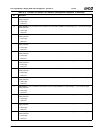
Offset 02h-03h Top Level PME/SMI Status Register (RO/RC) Reset Value: 0000h
Note: Reading this register clears all the SMI status bits except for the “read only” bits, because they have a second level of status
reporting. Clearing the second level status bits also clears the top level (except for GPIOs).
GPIO SMIs have third level of SMI status reporting at F0BAR0+I/O Offset 0Ch/1Ch. Clearing the third level GPIO status bits
also clears the second and top levels.
A read-only “Mirror” version of this register exists at F1BAR0+I/O Offset 00h. If the value of the register must be read without
clearing the SMI source (and consequently de-asserting SMI), F1BAR0+I/O Offset 00h can be read instead.
15 Suspend Modulation Enable Mirror. (Read to Clear)
This bit mirrors the Suspend Mode Configuration bit (F0 Index 96h[0]). It is used by the SMI handler to determine if the SMI
Speedup Disable Register (F1BAR0+I/O Offset 08h) must be cleared on exit.
14 SMI Source is USB. (Read to Clear) Indicates whether or not an SMI was caused by USB activity.
0: No.
1: Yes.
To enable SMI generation, set F5BAR0+I/O Offset 00h[20:19] to 11.
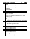
13 SMI Source is Warm Reset Command. (Read to Clear) Indicates whether or not an SMI was caused by Warm Reset
command.
0: No.
1: Yes.
12 SMI Source is NMI. (Read to Clear) Indicates whether or not an SMI was caused by NMI activity.
0: No.
1: Yes.
11 SMI Source is IRQ2 of SIO Module. (Read to Clear) Indicates whether or not an SMI was caused by IRQ2 of the SIO
module.
0: No.
1: Yes.
The next level (second level) of SMI status is reported in the SuperI/O module. See Table 5-29 "Banks 0 and 1 - Common
Control and Status Registers" on page 125 for details.
Table 6-33. F1BAR0+I/O Offset: SMI Status Registers (Continued)
Bit Description