


344 AMD Geode™ SC2200 Processor Data Book
Video Processor Module - Video Processor Registers - Function 4
32580B
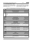
0 VID_EN (Video Enable). Enables video acceleration hardware.
0: Disable (reset) video module.
1: Enable.
Offset 04h-07h Display Configuration Register (R/W) Reset Value: x0000000h
General configuration register for display control. This register is also used to determine how graphics and video data are to be com-
bined in the display on the output device.
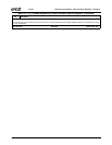
31 DDC_SDA_IN (DDC Input Data). (Read Only) Returns the value from the DDC_SDA signal (ball C20, muxed with
IDE_DATA9) connected to pin 12 of the VGA connector.
30:28 Reserved.
27 FP_ON_STATUS (Flat Panel On Status). (Read Only) Shows whether power to the attached flat panel is on or off. This bit
transitions at the end of the power-up or power-down sequence.
0: Power to the flat panel is off.
1: Power to the flat panel is on.
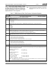
26 DAC_VREF (CRT DAC Voltage Reference). When set to 1, this bit enables use of an external voltage reference for CRT
DAC.
0: Disable external VREF. Enable Internal VREF.
1: Use external VREF. Connect an external voltage reference to the VREF signal (ball P1).
25 Reserved. Must be set to 0.
24 DDC_OE (DDC Output Enable). Selects the direction of signal DDC_SDA (ball C20, muxed with IDE_DATA9). This bit
indicates the direction of DDC data flow between the Video Processor and a CRT.
0: Input.
1: Output. DDC data is sent from the Video Processor to the CRT.
23 DDC_SDA_OUT (DDC Output Data). DDC data bit for output.
22 DDC_SCL (DDC Serial Clock). Provides the serial clock for the interface using the DDC_SCL signal (ball A20, muxed with
IDE_DATA10).
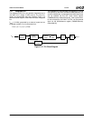
21 GV_GAMMA_SEL (Graphics or Video Gamma Source Data). Selects whether the graphics or video data goes to the
Gamma Correction RAM. GAMMA_EN (F4BAR0+Memory Offset 28h[0]) must be enabled for the selected data source to
pass through the Gamma Correction RAM.
0: Graphics data to Gamma Correction RAM.
1: Video data to Gamma Correction RAM.
Note: Gamma Correction is always in the RGB domain for graphics data.
Gamma Correction can be in the YUV or RGB domain for video data.
20 COLOR_CHROMA_SEL (Color or Chroma Key Select). Selects whether the graphics is used for color keying or the video
data stream is used for chroma keying.
0: Graphics data is compared to the color key.
1: Video data is compared to the chroma key.
19:17 PWR_SEQ_DLY (Power Sequence Delay). Selects the number of frame periods that transpire between successive transi-
tions of the power sequence control lines.
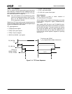
16:14 CRT_SYNC_SKW (CRT Sync Skew). Represents the number of pixel clocks to skew the horizontal and vertical sync that
are sent to the CRT. This field should be programmed to 100 at the baseline. Via this register, the sync can be moved for-
ward (later) or backward (earlier) relative to the pixel data. This register can be used to compensate for possible delay of
pixel data being processed via the Video Processor.
000: Sync moved 4 clocks backward 100: Baseline, sync not moved
001: Sync moved 3 clocks backward 101: Sync moved 1 clock forward
010: Sync moved 2 clocks backward 110: Sync moved 2 clocks forward
011: Sync moved 1 clock backward 111: Sync moved 3 clocks forward
13:10 Reserved.
9 CRT_VSYNC_POL (CRT Vertical Synchronization Polarity). Selects CRT vertical sync polarity.
0: CRT vertical sync is normally low, and is set high during the sync interval.
1: CRT vertical sync is normally high, and is set low during the sync interval.
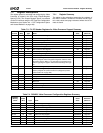
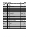
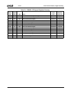
Table 7-7. F4BAR0+Memory Offset: Video Processor Configuration Registers (Continued)
Bit Description