


AMD Geode™ SC2200 Processor Data Book 387
Electrical Specifications
32580B
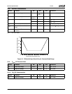
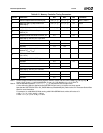
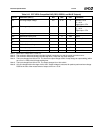
Table 9-15. CRT VESA Compatible DAC (RED, GREEN, and BLUE Outputs)
Symbol Parameter (Note 1) Min Max Unit Comments
V
FR
Full range output voltage 0.6 0.72 V SETRES = 470
R
L
= 37.5
Digital input = FFh
I
FR
Full range output current 16 19.2 mA SETRES = 470
R
L
= 37.5
Digital input = FFh
INL Integral linearity error ±1 LSB Note 2
DNL Differential linearity error ±1 LSB Note 3
t
ST
Full-scale settling time 10 ns CL = 40 pF, Note 4
t
R
Rise time 4 ns Note 5
DDM DAC to DAC matching 5 %
C
OUT
Max output capacitance 15 pF
PSRR Power supply rejection ratioNote 6 3.5 % At 0 to 1 MHz
Note 1. Black level = Blank level = 0 mA, 0V.
Note 2. The maximum difference between the ideal (straight) conversion line and the actual conversion curve.
Note 3. The maximum difference between the ideal step size (1 LSB) and any actual step size.
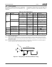
Note 4. The input changes from 00h to FFh. The time from output voltage at 50% of step change to output settling (within
an error of ±1 LSB) is the full-scale settling time.
Note 5. The input changes from 00h to FFh. The output changes from 10% to 90%.
Note 6. AV
CCRT
changes within the range of 3V to 3.6V. Output voltage is measured for peak-to-peak maximum change.
PSSR is the ratio of the measurement of output at AV
CCRT
= 3.3V.