


AMD Geode™ SC2200 Processor Data Book 293
Core Logic Module - USB Controller Registers - PCIUSB
32580B
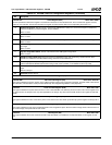
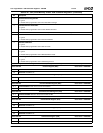
Index 06h-07h Status Register (R/W) Reset Value: 0280h
The PCI specification defines this register to record status information for PCI related events. This is a read/write register. However,
writes can only reset bits. A bit is reset whenever the register is written and the data in the corresponding bit location is a 1.
15 Detected Parity Error. This bit is set to 1 whenever the USB detects a parity error, even if the Parity Error (Response)
Detection Enable Bit (Command Register, bit 6) is disabled.
Write 1 to clear.
14 SERR# Status. This bit is set whenever the USB detects a PCI address error.
Write 1 to clear.
13 Received Master Abort Status. This bit is set when the USB, acting as a PCI master, aborts a PCI bus memory cycle.
Write 1 to clear.
12 Received Target Abort Status. This bit is set when a USB generated PCI cycle (USB is the PCI master) is aborted by a
PCI target.
Write 1 to clear.
11 Signaled Target Abort Status. This bit is set whenever the USB signals a target abort.
Write 1 to clear.
10:9 DEVSEL# Timing. (Read Only) These bits indicate the DEVSEL# timing when performing a positive decode. Since
DEVSEL# is asserted to meet the medium timing, these bits are encoded as 01b.
8 Data Parity Reported. (Read Only) This bit is set to 1 if the Parity Error Response bit (Command Register bit 6) is set,
and the USB detects PERR# asserted while acting as PCI master (whether or not PERR# was driven by USB).
7 Fast Back-to-Back Capable. The USB supports fast back-to-back transactions when the transactions are not to the same
agent.
This bit is always 1.
6:0 Reserved. Must be set to 0.
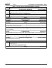
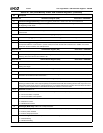
Index 08h Device Revision ID Register (RO) Reset Value: 08h
Index 09h-0Bh PCI Class Code Register (RO) Reset Value: 0C0310h
This register identifies the generic function of the USB the specific register level programming interface. The Base Class is 0Ch (Serial
Bus Controller). The Sub Class is 03h (Universal Serial Bus). The Programming Interface is 10h (OpenHCI).
Index 0Ch Cache Line Size Register (R/W) Reset Value: 00h
This register identifies the system cache-line size in units of 32-bit WORDs. The USB only stores the value of bit 3 in this register since
the cache-line size of 32 bytes is the only value applicable to the design. Any value other than 08h written to this register is read back
as 00h.
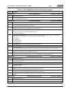
Index 0Dh Latency Timer Register (R/W) Reset Value: 00h
This register identifies the value of the latency timer in PCI clocks for PCI bus master cycles. Bits [2:0] of this register are always set to
0.
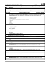
Index 0Eh Header Type Register (RO) Reset Value: 00h
This register identifies the type of the predefined header in the configuration space. Since the USB is a single function device and not a
PCI-to-PCI bridge, this byte should be read as 00h.
Index 0Fh BIST Register (RO) Reset Value: 00h
This register identifies the control and status of Built-In Self-Test (BIST). The USB does not implement BIST, so this register is read
only.
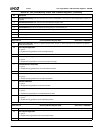
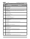
Table 6-41. PCIUSB: USB PCI Configuration Registers (Continued)
Bit Description