


110 AMD Geode™ SC2200 Processor Data Book
SuperI/O Module
32580B
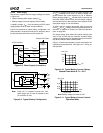
5.4.2.6 LDN 07h - Parallel Port
The Parallel Port supports all IEEE 1284 standard commu-
nication modes: Compatibility (known also as Standard or
SPP), Bidirectional (known also as PS/2), FIFO, EPP
(known also as Mode 4) and ECP (with an optional
Extended ECP mode).
The Parallel Port includes two groups of runtime registers,
as follows:
• A group of 21 registers at first level offset, sharing 14
entries. Three of these registers (at Offset 403h, 404h,
and 405h) are used only in the Extended ECP mode.
• A group of four registers, used only in the Extended ECP
mode, accessed by a second level offset.
The desired mode is selected by the ECR runtime register
(Offset 402h). The selected mode determines which runt-
ime registers are used and which address bits are used for
the base address. (See Section 5.8.1 on page 136 for fur-
ther details regarding the runtime registers.)
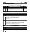
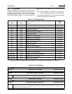
Table 5-15 lists the configuration registers which affect the
Parallel Port. Only the last register (F0h) is described here
(Table 5-16). See Table 5-3 "Standard Configuration Regis-
ters" on page 101 for descriptions of the others.
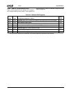
Table 5-15. Relevant Parallel Port Registers
Index Type Configuration Register or Action
Reset
Value
30h R/W Activate. See also bit 0 of the SIOCF1 register. 00h
60h R/W Base Address MSB register. Bits [7:3] (for A[15:11]) are RO, 00000b. Bit 2 (for A10)
should be 0b.
02h
61h R/W Base Address LSB register. Bits 1 and 0 (A1 and A0) are RO, 00b. For ECP Mode 4
(EPP) or when using the Extended registers, bit 2 (A2) should also be 0b.
78h
70h R/W Interrupt Number. 07h
71h R/W Interrupt Type.
Bits [7:2] are RO.
Bit 1 is R/W.
Bit 0 is RO. It reflects the interrupt type dictated by the Parallel Port operation mode.
This bit is set to 1 (level interrupt) in Extended Mode and cleared (edge interrupt) in all
other modes.
02h
74h R/W DMA Channel Select. 04h
75h RO Report no second DMA assignment. 04h
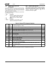
F0h R/W Parallel Port Configuration register. (See Table 5-16.) F2h
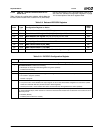
Table 5-16. Parallel Port Configuration Register
Bit Description
Index F0h Parallel Port Configuration Register (R/W) Reset Value: F2h
This register is reset by hardware to F2h.
7:5 Reserved. Must be 11.
4 Extended Register Access.
0: Registers at base (address)+403h, base+404h and base+405h are not accessible (reads and writes are ignored).
1: Registers at base (address)+403h, base+404h and base+405h are accessible. This option supports run-time configura-
tion within the Parallel Port address space.
3:2 Reserved.
1 Power Mode Control. When the logical device is active:
0: Parallel port clock disabled. ECP modes and EPP timeout are not functional when the logical device is active. Registers
are maintained.
1: Parallel port clock enabled. All operation modes are functional when the logical device is active. (Default)
0 TRI-STATE Control. When enabled and the device is inactive, the logical device output pins are in TRI-STATE.
0: Disable. (Default)
1: Enable.