


AMD Geode™ SC2200 Processor Data Book 209
Core Logic Module - Bridge, GPIO, and LPC Registers - Function 0
32580B
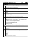
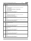
4:0 IOCS1# I/O Address Range. This 5-bit field is used to select the range of IOCS1#.
00000: 1 Byte 01111: 16 Bytes
00001: 2 Bytes 11111: 32 Bytes
00011: 4 Bytes All other combinations are reserved.
00111: 8 Bytes
Index 73h Reserved Reset Value: 00h
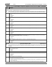
Index 74h-75h IOCS0# Base Address Register (R/W) Reset Value: 0000h
15:0 I/O Chip Select 0 Base Address. This 16-bit value represents the I/O base address used to enable the assertion of
IOCS0# (ball A10 - see PMR[23] in Table 4-2 on page 76).
This register is used in conjunction with F0 Index 76h (IOCS0# Control register).
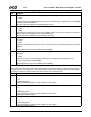
Index 76h IOCS0# Control Register (R/W) Reset Value: 00h
This register is used in conjunction with F0 Index 74h (IOCS0# Base Address register).
7 I/O Chip Select 0 Positive Decode (IOCS0#).
0: Disable.
1: Enable.
6 Writes Result in Chip Select. When this bit is set to 1, writes to configured I/O address (base address configured in F0
Index 74h; range configured in bits [4:0]) cause IOCS0# to be asserted.
0: Disable.
1: Enable.
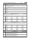
5 Reads Result in Chip Select. When this bit is set to 1, reads from configured I/O address (base address configured in F0
Index 74h; range configured in bits [4:0]) cause IOCS0# to be asserted.
0: Disable.
1: Enable.
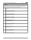
4:0 IOCS0# I/O Address Range. This 5-bit field is used to select the range of IOCS0#.
00000: 1 Byte 01111: 16 Bytes
00001: 2 Bytes 11111: 32 Bytes
00011: 4 Bytes All other combinations are reserved.
00111: 8 Bytes
Index 77h Reserved Reset Value: 00h
Index 78h-7Bh DOCCS# Base Address Register (R/W) Reset Value: 00000000h
31:0 DiskOnChip Chip Select Base Address. This 32-bit value represents the memory base address used to enable assertion
of DOCCS# (ball A9 or N31, see PMR[23] in Table 4-2 on page 76).
This register is used in conjunction with F0 Index 7Ch (DOCCS# Control register).
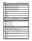
Index 7Ch-7Fh DOCCS# Control Register (R/W) Reset Value: 00000000h
This register is used in conjunction with F0 Index 78h (DOCCS# Base Address register).
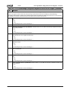
31:27 Reserved. Must be set to 0.
26 DiskOnChip Chip Select Positive Decode (DOCCS#).
0: Disable.
1: Enable.
25 Writes Result in Chip Select. When this bit is set to 1, writes to configured memory address (base address configured in
F0 Index 78h; range configured in bits [18:0]) cause DOCCS# to be asserted.
0: Disable.
1: Enable.
24 Reads Result in Chip Select. When this bit is set to 1, reads from configured memory address (base address configured in
F0 Index 78h; range configured in bits [18:0]) cause DOCCS# to be asserted.
0: Disable.
1: Enable.
23:19 Reserved. Must be set to 0.
18:0 DOCCS# Memory Address Range. This 19-bit mask is used to qualify accesses on which DOCCS# is asserted by mask-
ing the upper 19 bits of the incoming PCI address (AD[31:13]).
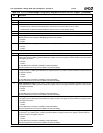
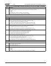
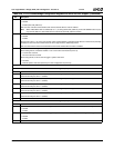
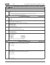
Table 6-29. F0: PCI Header/Bridge Configuration Registers for GPIO and LPC Support (Continued)
Bit Description