


AMD Geode™ SC2200 Processor Data Book 267
Core Logic Module - IDE Controller Registers - Function 2
32580B
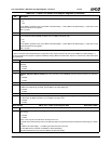
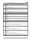
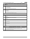
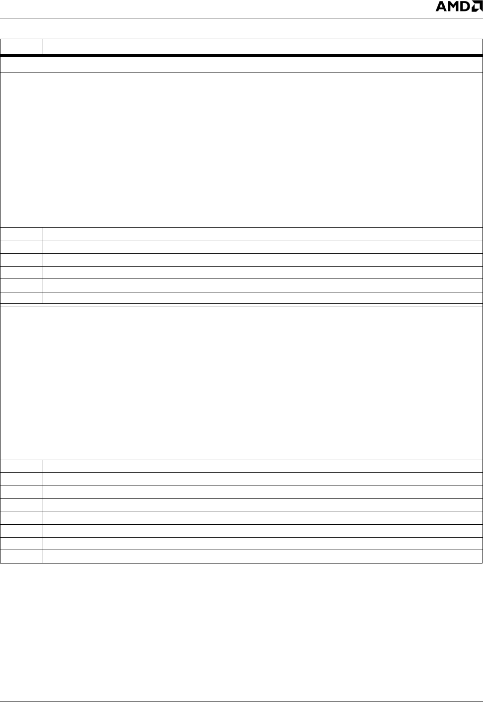
Index 40h-43h Channel 0 Drive 0 PIO Register (R/W) Reset Value: 00009172h
If Index 44h[31] = 0, Format 0. Bits [15:0] configure the same timing control for both command and data.
Format 0 settings for a Fast-PCI clock frequency of 33.3 MHz:
— PIO Mode 0 = 00009172h
— PIO Mode 1 = 00012171h
— PIO Mode 2 = 00020080h
— PIO Mode 3 = 00032010h
— PIO Mode 4 = 00040010h
Format 0 settings for a Fast-PCI clock frequency of 66.7 MHz:
— PIO Mode 0 = 0000FFF4h
— PIO Mode 1 = 0001F353h
— PIO Mode 2 = 00028141h
— PIO Mode 3 = 00034231h
— PIO Mode 4 = 00041131h
Note: All references to “cycle” in the following bit descriptions are to a Fast-PCI clock cycle.
31:20 Reserved. Must be set to 0.
19:16 PIOMODE. PIO mode.
15:12 t2I. Recovery time (value + 1 cycle).
11:8 t3. IDE_IOW# data setup time (value + 1 cycle).
7:4 t2W. IDE_IOW# width minus t3 (value + 1 cycle).
3:0 t1. Address Setup Time (value + 1 cycle).
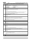
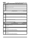
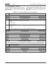
If Index 44h[31] = 1, Format 1. Bits [31:0] allow independent timing control for both command and data.
Format 1 settings for a Fast-PCI clock frequency of 33.3 MHz:
— PIO Mode 0 = 9172D132h
— PIO Mode 1 = 21717121h
— PIO Mode 2 = 00803020h
— PIO Mode 3 = 20102010h
— PIO Mode 4 = 00100010h
Format 1 settings for a Fast-PCI clock frequency of 66.7 MHz:
— PIO Mode 0 = F8E4F8E4h
— PIO Mode 1 = 53F3F353h
— PIO Mode 2 = 13F18141h
— PIO Mode 3 = 42314231h
— PIO Mode 4 = 11311131h
Note: All references to “cycle” in the following bit descriptions are to a Fast-PCI clock cycle.
31:28 t2IC. Command cycle recovery time (value + 1 cycle).
27:24 t3C. Command cycle IDE_IOW# data setup (value + 1 cycle).
23:20 t2WC. Command cycle IDE_IOW# pulse width minus t3 (value + 1 cycle).
19:16 t1C. Command cycle address setup time (value + 1 cycle).
15:12 t2ID. Data cycle recovery time (value + 1 cycle).
11:8 t3D. Data cycle IDE_IOW# data setup (value + 1 cycle).
7:4 t2WD. Data cycle IDE_IOW# pulse width minus t3 (value + 1 cycle).
3:0 t1D. Data cycle address Setup Time (value + 1 cycle).
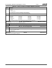
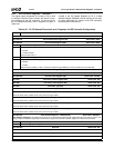
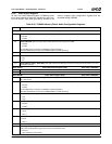
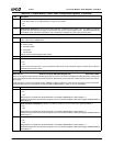
Table 6-35. F2: PCI Header/Channels 0 and 1 Registers for IDE Controller Configuration (Continued)
Bit Description