


234 AMD Geode™ SC2200 Processor Data Book
Core Logic Module - Bridge, GPIO, and LPC Registers - Function 0
32580B
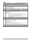
4 PME Edge/Level Select. Selects the type (edge or level) of the signal that issues a PME from the selected GPIO signal.
0: Edge input. (Default)
1: Level input.
For normal operation, always set this bit to 0 (edge input). Erratic system behavior results if this bit is set to 1.
See the note in the description of this register for more information about the default value of this bit.
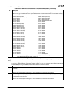
3 Lock. This bit locks the selected GPIO signal. Once this bit is set to 1 by software, it can only be cleared to 0 by power on
reset or by WATCHDOG reset.
0: No effect. (Default)
1: Direction, output type, pull-up and output value locked.
2 Pull-Up Control. Enables/disables the internal pull-up capability of the selected GPIO signal. It supports open-drain output
signals with internal pull-ups and TTL input signals.
0: Disable.
1: Enable. (Default)
Bits [1:0] of this register must = 01 for this bit to have effect.
1 Output Type. Controls the output buffer type (open-drain or push-pull) of the selected GPIO signal.
0: Open-drain. (Default)
1: Push-pull.
Bit 0 of this register must be set to 1 for this bit to have effect.
0 Output Enable. Indicates the GPIO signal output state. It has no effect on input.
0: TRI-STATE - Setting for GPIO to function as an input only. (Default)
1: Output enabled.
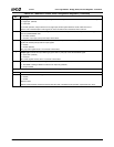
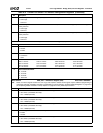
Offset 28h-2Bh GPIO Reset Control Register (R/W) Reset Value: 00000000h
31:1 Reserved. Must be set to 0.
0 GPIO Reset. Reset the GPIO logic.
0: Disable.
1: Enable.
Write 0 to clear.
This bit is level-sensitive and must be cleared after the reset is enabled (normal operation requires this bit to be 0).
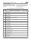
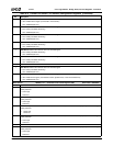
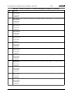
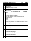
Table 6-30. F0BAR0+I/O Offset: GPIO Configuration Registers (Continued)
Bit Description