


AMD Geode™ SC2200 Processor Data Book 239
Core Logic Module - Bridge, GPIO, and LPC Registers - Function 0
32580B
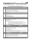
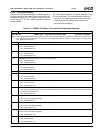
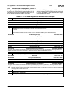
2 DRQ2 Source. Selects the interface source of the DRQ2 signal.
0: ISA - DRQ2 (unavailable externally).
1: LPC - LDRQ# (ball L28).
1 DRQ1 Source. Selects the interface source of the DRQ1 signal.
0: ISA - DRQ1 (unavailable externally).
1: LPC - LDRQ# (ball L28).
0 DRQ0 Source. Selects the interface source of the DRQ0 signal.
0: ISA - DRQ0 (unavailable externally).
1: LPC - LDRQ# (ball L28).
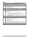
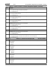
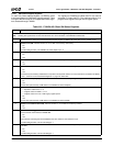
Offset 10h-13h LAD_EN — LPC Address Enable Register (R/W) Reset Value: 00000000h
31:18 Reserved.
17 LPC RTC. RTC addresses I/O Ports 070h-073h. See bit 16 for decode.
16 LPC/ISA Default Mapping. Works in conjunction with bits 17 and [14:0] of this register to enable mapping of specific
peripherals to LPC or internal ISA interfaces.
If bit [x] = 0 and bit 16 = 0 then: Transaction routed to internal ISA bus.
If bit [x] = 0 and bit 16 = 1 then: Transaction routed to LPC interface.
If bit [x] = 1 and bit 16 = 0 then: Transaction routed to LPC interface. Unclaimed I/O cycles do not go to ISA or LPC.
If bit [x] = 1 and bit 16 = 1 then: Transaction routed to internal ISA bus. Unclaimed I/O cycles go to LPC.
Bit [x] is defined as bits 17 and [14:0].
15 LPC ROM Addressing. Depends upon F0 Index 52h[2,0].
0: Disable.
1: Enable.
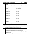
14 LPC Alternate SuperI/O Addressing. Alternate SuperI/O control addresses 4Eh-4Fh. See bit 16 for decode.
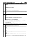
13 LPC SuperI/O Addressing. SuperI/O control addresses I/O Ports 2Eh-2Fh. See bit 16 for decode.
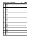
Note: This bit should not be routed to LPC when using the internal SuperI/O module and if IO_SIOCFG_IN (F5BAR0+I/O
Offset 00h[26:25]) = 10.
12 LPC Ad-Lib Addressing. Ad-Lib addresses I/O Ports 388h-389h. See bit 16 for decode.
11 LPC ACPI Addressing. ACPI microcontroller addresses I/O Ports 62h and 66h. See bit 16 for decode.
10 LPC Keyboard Controller Addressing. KBC addresses I/O Ports 60h and 64h.
Note: If this bit = 0 and bit 16 = 1, then F0 Index 5Ah[1] must be written 0.
9 LPC Wide Generic Addressing. Wide generic addresses. See bit 16 for decode.
Address selection made via F0BAR1+I/O Offset 18h[15:9]
Note: The selected range must not overlap any address range that is positively decoded by F0BAR1+I/O Offset 10h bits
[17], [14:10], and [8:0].
8 LPC Game Port 1 Addressing. Game Port 1 addresses. See bit 16 for decode.
Address selection made via F0BAR1+I/O Offset 14h[22:19]
7 LPC Game Port 0 Addressing. Game Port 0 addresses. See bit 16 for decode.
Address selection made via F0BAR1+I/O Offset 14h[18:15].
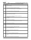
6 LPC Floppy Disk Controller Addressing. FDC addresses. See bit 16 for decode.
Address selection made via F0BAR1+I/O Offset 14h[14]
5 LPC Microsoft Sound System (MSS) Addressing. MSS addresses. See bit 16 for decode.
Address selection made via F0BAR1+I/O Offset 14h[13:12].
4 LPC MIDI Addressing. MIDI addresses. See bit 16 for decode.
Address selection made via F0BAR1+I/O Offset 14h[11:10].
3 LPC Audio Addressing. Audio addresses. See bit 16 for decode.
Address selection made via F0BAR1+I/O Offset 14h[9:8].
2 LPC Serial Port 1 Addressing. Serial Port 1 addresses. See bit 16 for decode.
Address selection made via F0BAR1+I/O Offset 14h[7:5].
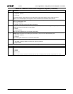
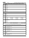
Table 6-31. F0BAR1+I/O Offset: LPC Interface Configuration Registers (Continued)
Bit Description