


214 AMD Geode™ SC2200 Processor Data Book
Core Logic Module - Bridge, GPIO, and LPC Registers - Function 0
32580B
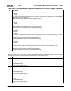
3 VGA Timer Enable. Turn on VGA Timer Count Register (F0 Index 8Eh) and generate an SMI when the timer reaches 0.
0: Disable.
1: Enable.
If an access occurs in the programmed address range, the timer is reloaded with the programmed count. F0 Index 8Bh[6]
selects the timebase for the VGA Timer.
SMI status is reported at F1BAR0+I/O Offset 00h/02h[6] (top level only).
2 Video Retrace Interrupt SMI. Allow SMI generation whenever video retrace occurs.
0: Disable.
1: Enable.
This information is decoded from the serial connection (PSERIAL register, bit 7) from the GX1 module. This function is nor-
mally not used for power management but for soft (VSA) VGA routines.
SMI status reporting is at F1BAR0+I/O Offset 00h/02h[5] (top level only).
1 General Purpose Timer 2 Enable. Turn on GP Timer 2 Count Register (F0 Index 8Ah) and generate an SMI when the
timer expires.
0: Disable.
1: Enable.
This idle timer is reloaded from the assertion of GPIO7 (if programmed to do so). GP Timer 2 programming is at F0 Index
8Bh[5,3,2].
Top level SMI status is reported at F1BAR0+I/O Offset 00h/02h[9].
Second level SMI status is reported at F1BAR0+I/O Offset 04h/06h[1].
0 General Purpose Timer 1 Enable. Turn on GP Timer 1 Count Register (F0 Index 88h) and generate an SMI when the
timer expires.
0: Disable.
1: Enable.
This idle timer’s load is multi-sourced and gets reloaded any time an enabled event (F0 Index 89h[6:0]) occurs.
GP Timer 1 programming is at F0 Index 8Bh[4].
Top level SMI status is reported at F1BAR0+I/O Offset 00h/02h[9].
Second level SMI status is reported at F1BAR0+I/O Offset 04h/06h[0].
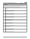
Index 84h Second Level PME/SMI Status Mirror Register 1 (RO) Reset Value: 00h
The bits in this register are used for the second level of status reporting. The top level is reported at F1BAR0+I/O Offset 00h/02h[0].
This register is called a "mirror" register since an identical register exists at F0 Index F4h. Reading this register does not clear the status,
while reading its counterpart at F0 Index F4h clears the status at both the second and the top levels.
7:3 Reserved. Reads as 0.
2 GPWIO2 SMI Status. Indicates whether or not an SMI was caused by a transition on the GPWIO2 pin.
0: No.
1: Yes.
To enable SMI generation:
1) Ensure that GPWIO2 is enabled as an input: F1BAR1+I/O Offset 15h[2] = 0.
2) Set F1BAR1+I/O Offset 15h[6] to 1.
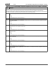
1 GPWIO1 SMI Status. Indicates whether or not an SMI was caused by a transition on the GPWIO1 pin.
0: No.
1: Yes.
To enable SMI generation:
1) Ensure that GPWIO1 is enabled as an input: F1BAR1+I/O Offset 15h[1] = 0.
2) Set F1BAR1+I/O Offset 15h[5] to 1.
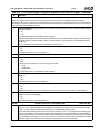
0 GPWIO0 SMI Status. Indicates whether or not an SMI was caused by a transition on the GPWIO0 pin.
0: No.
1: Yes.
To enable SMI generation:
1) Ensure that GPWIO0 is enabled as an input: F1BAR1+I/O Offset 15h[0] = 0.
2) Set F1BAR1+I/O Offset 15h[4] to 1.
Table 6-29. F0: PCI Header/Bridge Configuration Registers for GPIO and LPC Support (Continued)
Bit Description