


134 AMD Geode™ SC2200 Processor Data Book
SuperI/O Module
32580B
2 INTEN (Interrupt Enable).
0: ACB interrupt disabled.
1: ACB interrupt enabled. An interrupt is generated in response to one of the following events:
-Detection of an address match (ACBST[2] = 1) and ACBCTL1[6] = 1.
-Receipt of Bus Error (ACBST[5] = 1).
-Receipt of Negative Acknowledge after sending a byte (ACBST[4] = 1).
-Acknowledge of each transaction (same as the hardware set of the ACBST[6]).
-In master mode if ACBCTL1[7] = 1, after a successful start (ACBST[3] = 1).
-Detection of a Stop Condition while in slave mode (ACBST[7] = 1).
1 STOP (Stop).
0: Automatically cleared after Stop issued.
1: Setting this bit in master mode generates a Stop Condition to complete or abort current message transfer.
0 START (Start). Set this bit only when in master mode or when requesting master mode.
0: Cleared after Start Condition sent or Bus Error (ACBST[5] = 1) detected.
1: Single or repeated Start Condition generated on the ACCESS.bus. If the device is not the active master of the bus
(ACBST[1] = 0), setting START generates a Start Condition when the ACCESS.bus becomes free (ACBCST[1] = 0). An
address transmission sequence should then be performed.
If the device is the active master of the bus (ACBST[1] = 1), setting START and then writing to ACBSDA generates a
Start Condition. If a transmission is already in progress, a repeated Start Condition is generated. This condition can be
used to switch the direction of the data flow between the master and the slave, or to choose another slave device without
separating them with a Stop Condition.
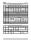
Offset 04h ACB Own Address Register - ACBADDR (R/W) Reset Value: xxh
7 SAEN (Slave Address Enable).
0: ACB does not check for an address match with ACBADDR[6:0].
1: ACBADDR[6:0] holds a valid address and enables the match of ADDR to an incoming address byte.
6:0 ADDR (Address). These bits hold the 7-bit device address of the SC2200. When in slave mode, the first 7 bits received
after a Start Condition are compared with this field (first bit received is compared with bit 6, and the last bit with bit 0). If the
address field matches the received data and ACBADDR[7] is 1, a match is declared.
Offset 05h ACB Control Register 2 - ACBCTL2 (R/W) Reset Value: 00h
This register enables/disables the functional block and determines the ACB clock rate.
7:1 ABCFRQ (ABC Frequency). This field defines the ABC period (low and high time) when the device serves as a bus mas-
ter. The clock low and high times are defined as follows:
tABCl = tABCh = 2*ABCFRQ*tCLK
where tCLK is the module input clock cycle, as defined in the Section 5.2 "Module Architecture" on page 97.
ABCFRQ can be programmed to values in the range of 0001000b through 1111111b. Using any other value has unpredict-
able results.
0 EN (Enable).
0: ACB is disabled, ACBCTL1, ACBST and ACBCST registers are cleared, and clocks are halted.
1: ACB is enabled.
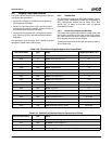
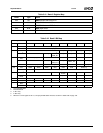
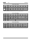
Table 5-32. ACB Registers (Continued)
Bit Description