


232 AMD Geode™ SC2200 Processor Data Book
Core Logic Module - Bridge, GPIO, and LPC Registers - Function 0
32580B
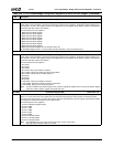
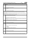
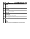
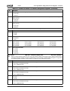
Offset 14h-17h GPDI1 — GPIO Data In 1 Register (RO) Reset Value: FFFFFFFFh
31:0 GPIO Data In. Bits [31:0] of this register correspond to GPIO63-GPIO32 signals, respectively. Reading each bit returns the
value of the corresponding GPIO signal, regardless of the signal configuration and the GPDO1 register (F0BAR0+I/O Offset
10h) value. Writes to this register are ignored.
0: Corresponding GPIO signal level low.
1: Corresponding GPIO signal level high.
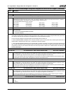
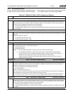
Offset 18h-1Bh GPIEN1 — GPIO Interrupt Enable 1 Register (R/W) Reset Value: 00000000h
31:16 Reserved. Must be set to 0.
15:0 GPIO Power Management Event (PME) Enable. Bits [15:0] of this register correspond to GPIO47-GPIO32 signals,
respectively. Each bit allows PME generation by the corresponding GPIO signal.
0: Disable PME generation.
1: Enable PME generation.
Notes: 1) All of the enabled GPIO PMEs are always reported at F1BAR1+I/O Offset 10h[3].
2) Any enabled GPIO PME can be selected to generate an SCI or SMI at F1BAR1+I/O Offset 0Ch[0].
If SCI is selected, the individually selected GPIO PMEs are globally enabled for SCI generation at F1BAR1+I/
O Offset 12h[3] and the status is reported at F1BAR1+I/O Offset 10h[3].
If SMI is selected, the individually selected GPIO PMEs generate an SMI and the status is reported at
F1BAR0+I/O Offset 00h/02h[0].
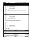
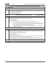
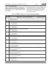
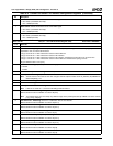
Offset 1Ch-1Fh GPST1 — GPIO Status 1 Register (R/W1C) Reset Value: 00000000h
31:16 Reserved. Must be set to 0.
15:0 GPIO Status. Bits [15:0] correspond to GPIO47-GPIO32 signals, respectively. Each bit reports a 1 when hardware detects
the edge (rising/falling on the GPIO signal) that is programmed in F0BAR0+I/O Offset 24h[5]. If the corresponding bit in
F0BAR0+I/O Offset 18h is set, this edge generates a PME.
0: No active edge detected since the bit was last cleared.
1: Active edge detected.
Writing 1 to the a Status bit clears it to 0.
This is the third level of SMI status reporting to the second level at F0 Index 87h/F7h[7] and the top level at F1BAR0+I/O
Offset 00h/02h[0]. Clearing the third level also clears the second and top levels.
This is the second level of SCI status reporting to the top level at F1BAR1+Offset 10h[3]. The status must be cleared at
both the this level and the top level (i.e., the top level is not automatically cleared when a bit in this register is cleared).
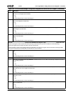
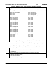
Offset 20h-23h GPIO Signal Configuration Select Register (R/W) Reset Value: 00000000h
31:6 Reserved. Must be set to 0.
Table 6-30. F0BAR0+I/O Offset: GPIO Configuration Registers (Continued)
Bit Description