


AMD Geode™ SC2200 Processor Data Book 409
Electrical Specifications
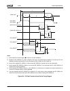
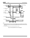
32580B
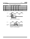
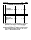
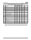
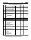
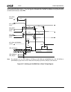
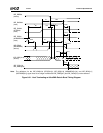
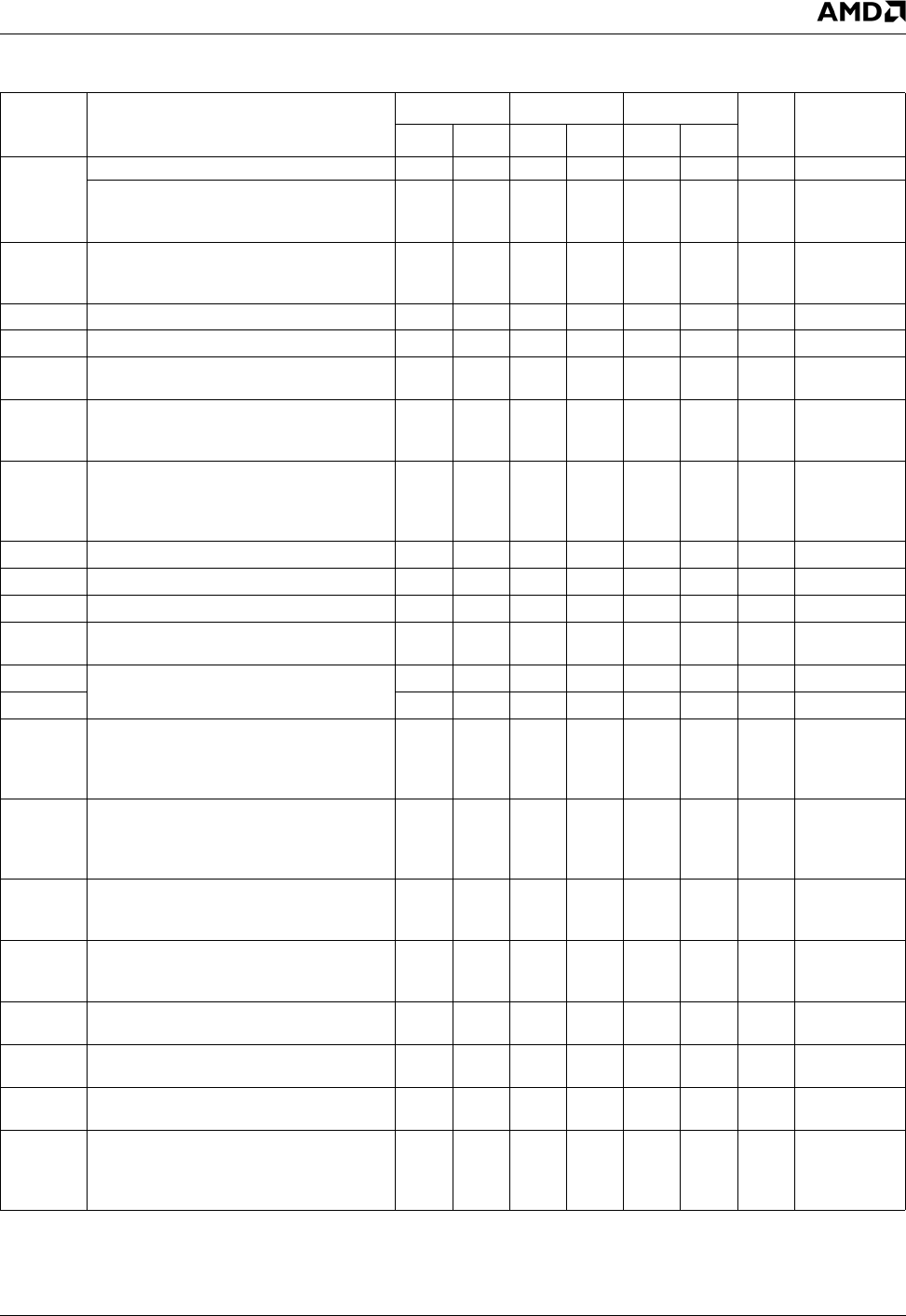
Table 9-28. IDE UltraDMA Data Burst Timing Parameters
Symbol Parameter
Mode 0 Mode 1 Mode 2
Unit CommentsMin Max Min Max Min Max
t
2CYC
Typical sustained average two cycle time 240 160 120 ns
Two cycle time allowing for clock variations
(from rising edge to next rising edge or from
falling edge to next falling edge of STROBE)
235 156 117 ns
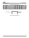
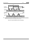
t
CYC
Cycle time allowing for asymmetry and clock
variations (from STROBE edge to STROBE
edge)
114 75 55 ns
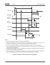
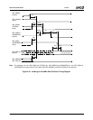
t
DS
Data setup time (at recipient) 15 10 7 ns
t
DH
Data hold time (at recipient) 5 5 5 ns
t
DVS
Data valid setup time at sender (from data
bus being valid until STROBE edge)
70 48 34 ns
t
DVH
Data valid hold time at sender (from
STROBE edge until data may become
invalid)
666ns
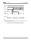
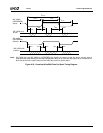
t
FS
First STROBE time (for device to first negate
IDE_IRDY[0:1] (DSTROBE[0:1]) from
IDE_IOW[0:1]# (STOP[0:1]) during a data in
burst)
0 230 0 200 0 170 ns
t
LI
Limited interlock time 0 150 0 150 0 150 ns Note 1
t
MLI
Interlock time with minimum 20 20 20 ns Note 1
t
UI
Unlimited interlock time 0 0 0 ns Note 1
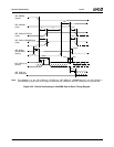
t
AZ
Maximum time allowed for output drivers to
release (from being asserted or negated)
10 10 10 ns
t
ZAH
Minimum delay time required for output driv-
ers to assert or negate (from released state)
20 20 20 ns
t
ZAD
000ns
t
ENV
Envelope time (from IDE_DACK[0:1]# to
IDE_IOW[0:1]# (STOP[0:1]) and
IDE_IOR[0:1]# (HDMARDY[0:1]#) during
data out burst initiation)
20 70 20 70 20 70 ns
t
SR
STROBE to DMARDY time (if DMARDY# is
negated before this long after STROBE
edge, the recipient receives no more than
one additional data WORD)
50 30 20 ns
t
RFS
Ready-to-final-STROBE time (no STROBE
edges are sent this long after negation of
DMARDY#)
75 60 50 ns
t
RP
Ready-to-pause time (time that recipient
waits to initiate pause after negating
DMARDY#)
160 125 100 ns
t
IORDYZ
Pull-up time before allowing IDE_IORDY[0:1]
to be released
20 20 20 ns
t
ZIORDY
Minimum time device waits before driving
IDE_IORDY[0:1]
000ns
t
ACK
Setup and hold times for IDE_DACK[0:1]#
(before assertion or negation)
20 20 20 ns
t
SS
Time from STROBE edge to negation of
IDE_DREQ[0:1] or assertion of
IDE_IOW[0:1]# (STOP[0:1]) (when sender
terminates a burst)
50 50 50 ns
Note 1. t
UI
, t
MLI
, and t
LI
indicate sender-to-recipient or recipient-to-sender interlocks, that is, one agent (either sender or recipient) is wait-
ing for the other agent to respond with a signal before proceeding. t
UI
is an unlimited interlock with no maximum time value. t
MLI
is a limited timeout with a defined minimum. t
LI
is a limited time-out with a defined maximum.