


AMD Geode™ SC2200 Processor Data Book 199
Core Logic Module - Bridge, GPIO, and LPC Registers - Function 0
32580B
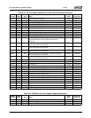
4 Memory Write and Invalidate. Allow the Core Logic module to do memory write and invalidate cycles, if the PCI Cache
Line register (F0 Index 0Ch) is set to 32 bytes (08h).
0: Disable. (Default)
1: Enable.
3 Special Cycles. Allow the Core Logic module to respond to special cycles.
0: Disable.
1: Enable. (Default)
This bit must be enabled to allow an SMI to be generated from a CPU Shutdown cycle.
2 Special Cycles. Allow the Core Logic module to respond to special cycles.
0: Disable.
1: Enable. (Default)
This bit must be enabled to allow the internal CPU Warm Reset signal to be triggered from a CPU Shutdown cycle.
1 Memory Space. Allow the Core Logic module to respond to memory cycles from the PCI bus.
0: Disable.
1: Enable. (Default)
0 I/O Space. Allow the Core Logic module to respond to I/O cycles from the PCI bus:
0: Disable.
1: Enable. (Default)
This bit must be set to 1 to access I/O offsets through F0BAR0 and F0BAR1 (see F0 Index 10h and 14h).
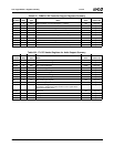
Index 06h-07h PCI Status Register (R/W) Reset Value: 0280h
15 Detected Parity Error. This bit is set whenever a parity error is detected.
Write 1 to clear.
14 Signaled System Error. This bit is set whenever the Core Logic module asserts SERR# active.
Write 1 to clear.
13 Received Master Abort. This bit is set whenever a master abort cycle occurs. A master abort occurs when a PCI cycle is
not claimed, except for special cycles.
Write 1 to clear.
12 Received Target Abort. This bit is set whenever a target abort is received while the Core Logic module is the master for the
PCI cycle.
Write 1 to clear.
11 Signaled Target Abort. This bit is set whenever the Core Logic module signals a target abort. This occurs when an
address parity error occurs for an address that hits in the active address decode space of the Core Logic module.
Write 1 to clear.
10:9 DEVSEL# Timing. (Read Only) These bits are always 01, as the Core Logic module always responds to cycles for which it
is an active target with medium DEVSEL# timing.
00: Fast.
01: Medium.
10: Slow.
11: Reserved.
8 Data Parity Detected. This bit is set when:
1) The Core Logic module asserts PERR# or observed PERR# asserted.
2) The Core Logic module is the master for the cycle in which the PERR# occurred, and PE is set (F0 Index 04h[6] = 1).
Write 1 to clear.
7 Fast Back-to-Back Capable. (Read Only) Enables the Core Logic module, as a target, to accept fast back-to-back trans-
actions.
0: Disable.
1: Enable.
This bit is always set to 1.
6:0 Reserved. (Read Only) Must be set to 0 for future use.
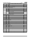
Table 6-29. F0: PCI Header/Bridge Configuration Registers for GPIO and LPC Support (Continued)
Bit Description