


AMD Geode™ SC2200 Processor Data Book 381
Electrical Specifications
32580B
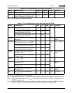
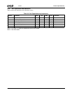
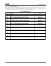
9.3 AC Characteristics
The tables in this section list the following AC characteris-
tics:
• Output delays
• Input setup requirements
• Input hold requirements
• Output float delays
• Power-up sequencing requirements
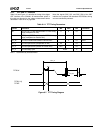
The default levels for measurement of the rising clock edge
reference voltage (V
REF
), and other voltages are shown in
Table 9-16. Input or output signals must cross these levels
during testing. Unless otherwise specified, all measure-
ment points in this section conform to these default levels.
All AC tests are at V
IO
= 3.14V to 3.46V (3.3V nominal),
T
C
= 0
o
C to 85
o
C, C
L
= 50 pF, unless otherwise specified.
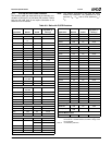
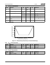
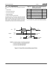
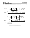
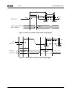
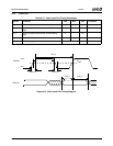
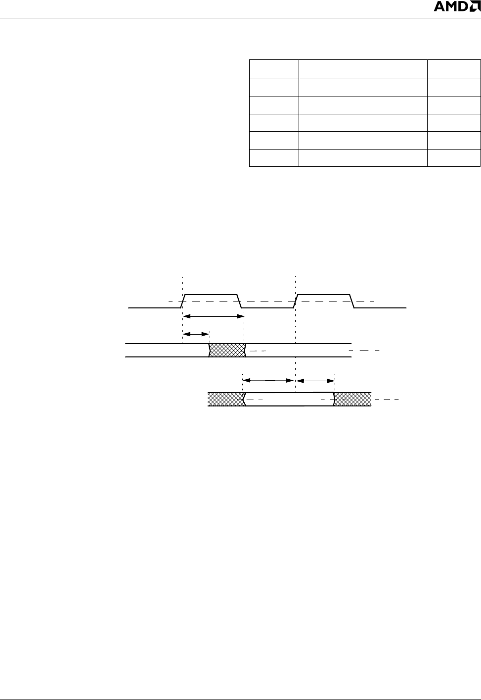
Figure 9-2. General Drive level and Measurement Points
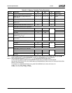
Table 9-11. Default Levels for Measurement of
Switching Parameters
Symbol Parameter Value (V)
V
REF
Reference Voltage 1.5
V
IHD
Input High Drive Voltage 2.0
V
ILD
Input Low Drive Voltage 0.8
V
OHD
Output High Drive Voltage 2.4
V
OLD
Output Low Drive Voltage 0.4
CLK
Outputs
Inputs
V
IHD
V
ILD
V
REF
Valid Input
Valid Output
n+1
Valid Output
n
V
REF
V
REF
V
ILD
V
IHD
Min
Max
Legend: A = Maximum Output or Float Delay Specification
B = Minimum Output or Float Delay Specification
C = Minimum Input Setup Specification
D = Minimum Input Hold Specification
T
X
B
A
CD
V
OHD
V
OLD