


AMD Geode™ SC2200 Processor Data Book 115
SuperI/O Module
32580B
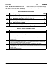
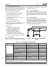
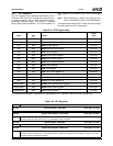
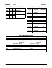
5.5.2.7 System Power States
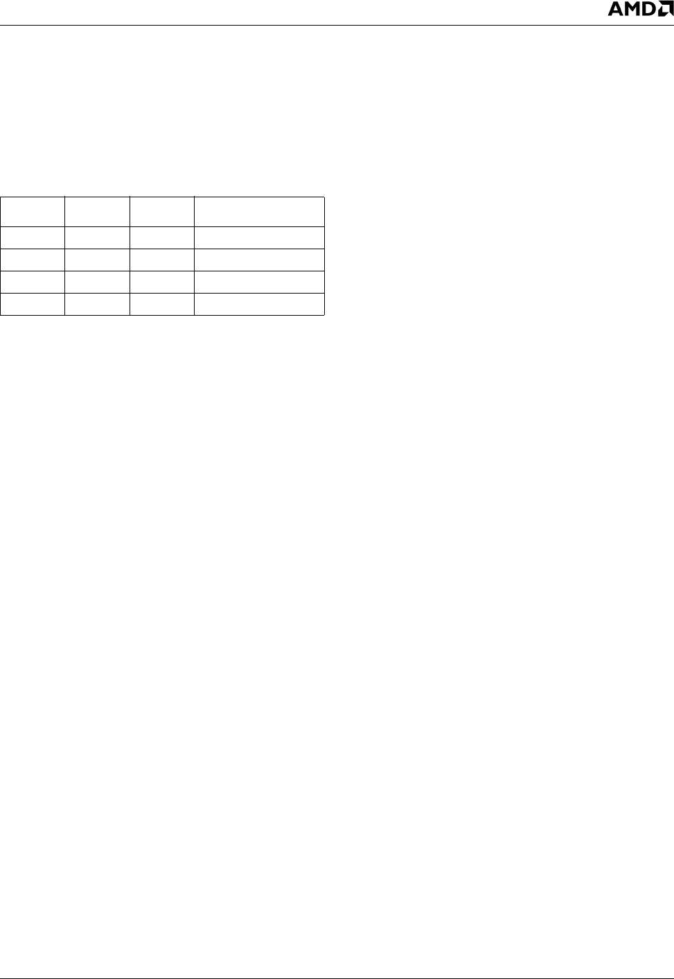
The system power state may be No Power, Power On,
Power Off or Power Failure. Table 5-18 indicates the power-
source combinations for each state. No other power-source
combinations are valid.
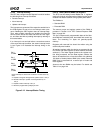
In addition, the power sources and distribution for the entire
system are illustrated in Figure 5-8 on page 114.
No Power
This state exists when no external or battery power is con-
nected to the device. This condition does not occur once a
backup battery has been connected, except in the case of
a malfunction.
Power On
This is the normal state when the system is active. This
state may be initiated by various events in addition to the
normal physical switching on of the system. In this state,
the system power supply is powered by external AC power
and produces V
DIGITAL
and V
SB
. The system and the part
are powered by V
DIGITAL,
with the exception of the RTC log-
ical device, which is powered by V
SB.
Power Off (Suspended)
This is the normal state when the system has been
switched off and is not required to be active, but is still con-
nected to a live external AC input power source. This state
may be initiated directly or by software. The system is pow-
ered down. The RTC logical device remains active, pow-
ered by V
SB
.
Power Failure
This state occurs when the external power source to the
system stops supplying power, due to disconnection or
power failure on the external AC input power source. The
RTC continues to maintain timekeeping and RAM data
under battery power (V
BAT
), unless the oscillator stop bit
was set in the RTC. In this case, the oscillator stops func-
tioning if the system goes to battery power, and timekeep-
ing data becomes invalid.
System Bus Lockout
During power on or power off, spurious bus transactions
from the host may occur. To protect the RTC internal regis-
ters from corruption, all inputs are automatically locked out.
The lockout condition is asserted when V
SB
is lower than
V
SBON
.
Power-Up Detection
When system power is restored after a power failure or
power off state (V
SB
= 0), the lockout condition continues
for a delay of 62 msec (minimum) to 125 msec (maximum)
after the RTC switches from battery to system power.
The lockout condition is switched off immediately in the fol-
lowing situations:
• If the Divider Chain Control bits, DV[2:0], (CRA bits [6:4])
specify a normal operation mode (01x or 100), all input
signals are enabled immediately upon detection of
system voltage above V
SBON
.
• When battery voltage is below V
BATDCT
and HMR is 1,
all input signals are enabled immediately upon detection
of system voltage above V
SBON
. This also initializes
registers at offsets 00h through 0Dh.
• If bit 7 (VRT) of CRD is 0, all input signals are enabled
immediately upon detection of system voltage above
V
SBON
.
5.5.2.8 Oscillator Activity
The RTC oscillator is active if:
• V
SB
power supply is higher than V
SBON
, independent of
the battery voltage, V
BAT
-or-
• V
BAT
power supply is higher than V
BATMIN
, regardless if
V
SB
is present or not.
The RTC oscillator is disabled if:
• During power-down (V
BAT
only), the battery voltage
drops below V
BATMIN
. When this occurs, the oscillator
may be disabled and its functionality cannot be guaran-
teed.
-or-
• Software wrote 00x to DV[2:0] bits of the CRA Register
and V
SB
is removed. This disables the oscillator and
decreases the power consumption from the battery
connected to V
BAT
. When disabling the oscillator, the
CMOS RAM is not affected as long as the battery is
present at a correct voltage level.
If the RTC oscillator becomes inactive, the following fea-
tures are dysfunctional/disabled:
• Timekeeping
• Periodic interrupt
• Alarm
Table 5-18. System Power States
V
DIGITAL
V
SB
V
BAT
Power State
−−−No Power
−−+ Power Failure
− + + or - Power Off
+ + + or - Power On