AMD Geode™ SC2200 Processor Data Book 151
Core Logic Module
32580B
6.2.1 Fast-PCI Interface to External PCI Bus
The Core Logic module provides a PCI bus interface that is
both a slave for PCI cycles initiated by the GX1 module or
other PCI master devices, and a non-preemptive master for
DMA transfer cycles. It is also a standard PCI master for
the IDE controllers and audio I/O logic. The Core Logic
supports positive decode for configurable memory and I/O
regions, and implements a subtractive decode option for
unclaimed PCI accesses. It also generates address and
data parity, and performs parity checking. The arbiter for
the Fast-PCI interface is located in the GX1 module.
Configuration registers are accessed through the PCI inter-
face using the PCI Bus Type 1 configuration mechanism as
described in the PCI Specification.
6.2.1.1 Processor Mastered Cycles
The Core Logic module acts on all processor initiated
cycles according to PCI rules for active/subtractive decode
using DEVSEL#. Memory writes are automatically posted.
Reads are retried if they are not destined for actively
decoded (i.e., positive decode) devices on the high speed
X-Bus or the 33 MHz X-Bus. This means that reads to
external PCI, LPC, or Sub-ISA devices are automatically
treated as delayed transactions through the PCI retry
mechanism. This allows the high bandwidth devices
access to the Fast-PCI interface while the response from a
slow device is accumulated.
Bursting from the host is not supported.
All types of configuration cycles are supported and handled
appropriately according to the PCI specification.
6.2.1.2 External PCI Mastered Cycles
Memory cycles mastered by external PCI devices on the
external PCI bus are actively taken if they are to the system
memory address range. Memory cycles to system memory
are forwarded to the Fast-PCI interface. Burst transfers are
stopped on every cache line boundary to allow efficient
buffering in the Fast-PCI interface block.
I/O and configuration cycles mastered by external PCI
devices which are subtractively decoded by the Core Logic
module, are not handled.
6.2.1.3 Core Logic Internal or Sub-ISA Mastered
Cycles
Only memory cycles (not I/O cycles) are supported by the
internal Sub-ISA or legacy DMA masters. These memory
cycles are always forwarded to the Fast-PCI interface.
6.2.1.4 External PCI Bus
The external PCI bus is a fully-compliant PCI bus. PCI slots
are connected to this bus. Support for up to two bus mas-
ters is provided. The arbiter is in the Core Logic module.
6.2.1.5 Bus Master Request Priority
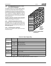
The Fast-PCI bus supports seven bus masters. The
requests (REQs) are fixed in priority. The seven bus mas-
ters in order of priority are:
1) VIP
2) IDE Channel 0
3) IDE Channel 1
4) Audio
5) USB
6) External REQ0#
7) External REQ1#
6.2.2 PSERIAL Interface
The majority of the system power management logic is
implemented in the Core Logic module, but a minimal
amount of logic is contained within the GX1 module to pro-
vide information that is not externally visible (e.g., graphics
controller).
The GX1 module implements a simple serial communica-
tions mechanism to transmit the CPU status to the Core
Logic module via internal signal PSERIAL. The GX1 mod-
ule accumulates CPU events in an 8-bit register which it
transmits serially every 1 to 10 µs.
The packet transmitter holds the serial output internal sig-
nal (PSERIAL) low until the transmission interval counter
has elapsed. Once the counter has elapsed, the PSERIAL
signal is held high for two clocks to indicate the start of
packet transmission. The contents of the Serial Packet reg-
ister are then shifted out starting from bit 7 down to bit 0.
The PSERIAL signal is held high for one clock to indicate
the end of packet transmission and then remains low until
the next transmission interval. After the packet transmis-
sion is complete, the GX1 module’s Serial Packet register’s
contents are cleared.
The GX1 module’s input clock is used as the clock refer-
ence for the serial packet transmitter.
Once a bit in the register is set, it remains set until the com-
pletion of the next packet transmission. Successive events
of the same type that occur between packet transmissions
are ignored. Multiple unique events between packet trans-
missions accumulate in this register. The GX1 module
transmits the contents of the serial packet only when a bit
in the Serial Packet register is set and the interval counter
has elapsed.
The Core Logic module decodes the serial packet after
each transmission and performs the power management
tasks related to video retrace.
For more information on the Serial Packet register refer to
the AMD Geode™ GX1 Processor Data Book.


