


410 AMD Geode™ SC2200 Processor Data Book
Electrical Specifications
32580B
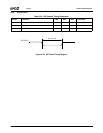
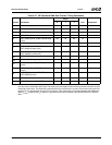
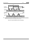
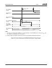
All timing parameters are measured at the connector of the device to which the parameter applies. For example, the sender
stops generating STROBE edges t
RFS
after the negation of DMARDY. Both STROBE and DMARDY timing measurements
are taken at the connector of the sender.
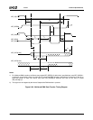
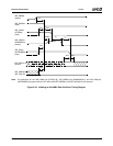
Figure 9-27. Initiating an UltraDMA Data in Burst Timing Diagram
t
UI
t
ACK
t
ENV
t
FS
t
FS
t
ZAD
t
ACK
t
ZIORDY
t
AZ
t
ACK
t
DVS
t
DVH
t
ENV
t
ZAD
IDE_DATA[15:0]
IDE_ADDR[2:0]
IDE_CS[0:1]
IDE_REQ0
(device)
IDE_DACK0#
(host)
IDE_IOW0#
(STOP0)
(host)
IDE_IOR0#
(HDMARDY0#)
(host)
IDE_IRDY0 (DSTROBE0)
(device)
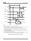
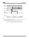
Note: The definitions for the IDE_IOW[0:1]# (STOP[0:1]), IDE_IOR[0:1]# (HDMARDY[0:1]#) and IDE_IRDY[0:1]
(DSTROBE[0:1]) signal lines are not in effect until IDE_REQ[0:1] and IDE_DACK[0:1]# are asserted.