


206 AMD Geode™ SC2200 Processor Data Book
Core Logic Module - Bridge, GPIO, and LPC Registers - Function 0
32580B
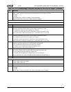
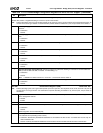
Index 5Ah Decode Control Register 1 (R/W) Reset Value: 01h
Indicates PCI positive or negative decoding for various I/O ports on the ISA bus.
Note: Positive decoding by the Core Logic module speeds up I/O cycle time. The I/O ports mentioned in the bit descriptions below, do
not exist in the Core Logic module. It is assumed that if positive decode is enabled for a port, the port exists on the ISA bus.
7 Secondary Floppy Positive Decode. Selects PCI positive or subtractive decoding for accesses to I/O ports 372h-375h
and 377h.
0: Subtractive.
1: Positive.
6 Primary Floppy Positive Decode. Selects PCI positive or subtractive decoding for accesses to I/O ports 3F2h-3F5h and
3F7h.
0: Subtractive.
1: Positive.
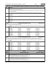
5 COM4 Positive Decode. Selects PCI positive or subtractive decoding for accesses to I/O ports 2E8h-2EFh.
0: Subtractive.
1: Positive.
4 COM3 Positive Decode. Selects PCI positive or subtractive decoding for accesses to I/O ports 3E8h-3EFh.
0: Subtractive.
1: Positive.
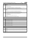
3 COM2 Positive Decode. Selects PCI positive or subtractive decoding for accesses to I/O ports 2F8h-2FFh.
0: Subtractive.
1: Positive.
2 COM1 Positive Decode. Selects PCI positive or subtractive decoding for accesses to I/O ports 3F8h-3FFh.
0: Subtractive.
1: Positive.
1 Keyboard Controller Positive Decode. Selects PCI positive or subtractive decoding for accesses to I/O Ports 060h and
064h (as well as 062h and 066h, if enabled - F4 Index 5Bh[7] = 1).
0: Subtractive.
1: Positive.
Note: If F0BAR1+I/O Offset 10h bits 10 = 0 and 16 = 1, then this bit must be written 0.
0 Real-Time Clock Positive Decode. Selects PCI positive or subtractive decoding for accesses to I/O Ports 070h-073h.
0: Subtractive.
1: Positive.
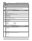
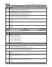
Index 5Bh Decode Control Register 2 (R/W) Reset Value: 20h
Note: Positive decoding by the Core Logic module speeds up the I/O cycle time. The Keyboard, LPT3, LPT2, and LPT1 I/O ports do
not exist in the Core Logic module. It is assumed that if positive decoding is enabled for any of these ports, the port exists on
the ISA bus.
7 Keyboard I/O Port 062h/066h Positive Decode. This alternate port to the keyboard controller is provided in support of
power management features.
0: Disable.
1: Enable.
6 Reserved. Must be set to 0.
5 BIOS ROM Positive Decode. Selects PCI positive or subtractive decoding for accesses to the configured ROM space.
0: Subtractive.
1: Positive.
ROM configuration is at F0 Index 52h[2:0].
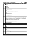
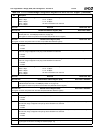
4 Secondary IDE Controller Positive Decode. Selects PCI positive or subtractive decoding for accesses to I/O ports 170h-
177h and 376h-377h (excluding writes to 377h).
0: Subtractive. Subtractively decoded IDE addresses are forwarded to the PCI slot bus. If a master abort occurs, they are
then forwarded to ISA.
1: Positive. Positively decoded IDE addresses are forwarded to the internal IDE controller and then to the IDE bus.
Table 6-29. F0: PCI Header/Bridge Configuration Registers for GPIO and LPC Support (Continued)
Bit Description