


88 AMD Geode™ SC2200 Processor Data Book
General Configuration Block
32580B
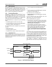
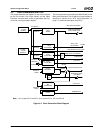
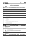
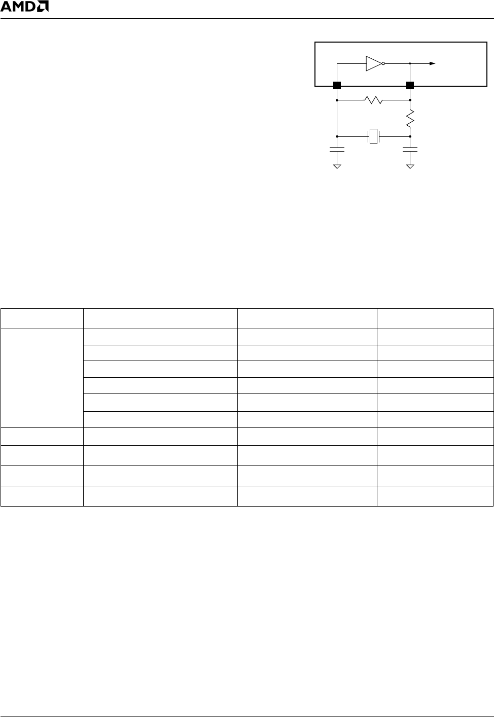
4.5.1 27 MHz Crystal Oscillator
The internal oscillator employs an external crystal con-
nected to the on-chip amplifier. The on-chip amplifier is
accessible on the X27I input and X27O output signals. See
Figure 4-3 for the recommended external circuit and Table
4-5 for a list of the circuit components.
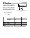
Choose C
1
and C
2
capacitors to match the crystal’s load
capacitance. The load capacitance C
L
“seen” by crystal Y
is comprised of C
1
in series with C
2
and in parallel with the
parasitic capacitance of the circuit. The parasitic capaci-
tance is caused by the chip package, board layout and
socket (if any), and can vary from 0 to 10 pF. The rule of
thumb in choosing these capacitors is:
C
L
= (C
1
* C
2
) / (C
1
+ C
2
) + C
PARASITIC
Example 1:
Crystal C
L
= 10 pF, C
PARASITIC
= 8.2 pF
C
1
= 3.6 pF, C
2
= 3.6 pF
Example 2:
Crystal C
L
= 20 pF, C
PARASITIC
= 8 pF
C
1
= 24 pF, C
2
= 24 pF
Figure 4-3. Recommended Oscillator External
Circuitry
Internal
External
R
2
X27I
X27O
C
1
C
2
R
1
Y
To other
modules
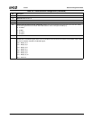
Table 4-5. Crystal Oscillator Circuit Components
Component Parameters Values Tolerance
Crystal Resonance Frequency 27.00 MHz Parallel mode 50 PPM or better
Type AT-cut or BT-cut
Serial Resistance 40 Ω Max
Shunt Capacitance 7 pF Max
Load Capacitance, C
L
10-20 pF
Temperature Coefficient User-defined
Resistor R
1
Resistance 20 MΩ 5%
Resistor R
2
1
Resistance 100 Ω 5%
Capacitor C
1
1
Capacitance 3-24 pF 5%
Capacitor C
2
1
Capacitance 3-24 pF 5%
1. The value of these components is recommended. It should be tuned according to crystal and board parameters.