


268 AMD Geode™ SC2200 Processor Data Book
Core Logic Module - IDE Controller Registers - Function 2
32580B
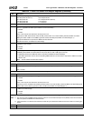
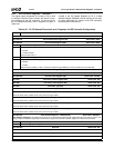
Index 44h-47h Channel 0 Drive 0 DMA Control Register (R/W) Reset Value: 00077771h
The structure of this register depends on the value of bit 20.
If bit 20 = 0, Multiword DMA
Settings for a Fast-PCI clock frequency of 33.3 MHz:
— Multiword DMA Mode 0 = 00077771h
— Multiword DMA Mode 1 = 00012121h
— Multiword DMA Mode 2 = 00002020h
Settings for a Fast-PCI clock frequency of 66.7 MHz:
— Multiword DMA Mode 0 = 000FFFF3h
— Multiword DMA Mode 1 = 00035352h
— Multiword DMA Mode 2 = 00015151h
Note: All references to “cycle” in the following bit descriptions are to a Fast-PCI clock cycle.
31 PIO Mode Format. This bit sets the PIO mode format for all channels and drives. Bit 31 of Offsets 2Ch, 34h, and 3Ch are R/
W, but have no function so are defined as reserved.
0: Format 0.
1 Format 1.
30:21 Reserved. Must be set to 0.
20 DMA Select. Selects type of DMA operation. 0: Multiword DMA
19:16 tKR. IDE_IOR# recovery time (4-bit) (value + 1 cycle).
15:12 tDR. IDE_IOR# pulse width (value + 1 cycle).
11:8 tKW. IDE_IOW# recovery time (4-bit) (value + 1 cycle).
7:4 tDW. IDE_IOW# pulse width (value + 1 cycle).
3:0 tM. IDE_CS[1:0]# to IDE_IOR#/IOW# setup; IDE_CS[1:0]# setup to IDE_DACK0#/DACK1#.
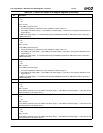
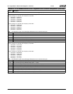
If bit 20 = 1, UltraDMA
Settings for a Fast-PCI clock frequency of 33.3 MHz:
— UltraDMA Mode 0 = 00921250h
— UltraDMA Mode 1 = 00911140h
— UltraDMA Mode 2 = 00911030h
Settings for a Fast-PCI clock frequency of 66.7 MHz:
— UltraDMA Mode 0 = 009436A1h
— UltraDMA Mode 1 = 00933481h
— UltraDMA Mode 2 = 00923261h
Note: All references to “cycle” in the following bit descriptions are to a Fast-PCI clock cycle.
31 PIO Mode Format. This bit sets the PIO mode format for all channels and drives. Bit 31 of Offsets 2Ch, 34h, and 3Ch are R/
W, but have no function so are defined as reserved.
0: Format 0.
1: Format 1.
30:24 Reserved. Must be set to 0.
23:21 BSIZE. Input buffer threshold.
20 DMA Select. Selects type of DMA operation. 1: UltraDMA.
19:16 tCRC. CRC setup UDMA in IDE_DACK# (value + 1 cycle) (for host terminate CRC setup = tMLI + tSS).
15:12 tSS. UDMA out (value + 1 cycle).
11:8 tCYC. Data setup and cycle time UDMA out (value + 2 cycles).
7:4 tRP. Ready to pause time (value + 1 cycle). Note: tRFS + 1 tRP on next clock.
3:0 tACK. IDE_CS[1:0]# setup to IDE_DACK0#/DACK1# (value + 1 cycle).
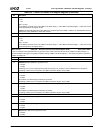
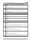
Index 48h-4Bh Channel 0 Drive 1 PIO Register (R/W) Reset Value: 00009172h
Channel 0 Drive 1 Programmed I/O Control Register. See F2 Index 40h for bit descriptions.
Index 4Ch-4Fh Channel 0 Drive 1 DMA Control Register (R/W) Reset Value: 00077771h
Channel 0 Drive 1 MDMA/UDMA Control Register. See F2 Index 44h for bit descriptions.
Note: The PIO Mode format is selected in F2 Index 44h[31], bit 31 of this register is defined as reserved.
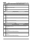
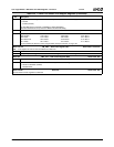
Table 6-35. F2: PCI Header/Channels 0 and 1 Registers for IDE Controller Configuration (Continued)
Bit Description