


84 AMD Geode™ SC2200 Processor Data Book
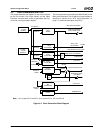
General Configuration Block
32580B
WATCHDOG Interrupt
The WATCHDOG interrupt (if configured and enabled) is
routed to an IRQ signal. The IRQ signal is programmable
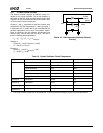
via the INTSEL register (Offset 38h, described in Table 4-2
"Multiplexing, Interrupt Selection, and Base Address Regis-
ters" on page 76). The WATCHDOG interrupt is a share-
able, active low, level interrupt.
WATCHDOG SMI
The WATCHDOG SMI is recognized by the Core Logic
module as internal input signal EXT_SMI0#. To use the
WATCHDOG SMI, Core Logic registers must be configured
appropriately.
4.3.2 WATCHDOG Registers
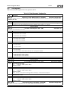
Table 4-3 describes the WATCHDOG registers.
4.3.2.1 Usage Hints
• SMM code should set bit 8 of the WDCNFG register to 1
when entering ACPI C3 state, if the WATCHDOG timer
is to be suspended. If this is not done, the WATCHDOG
timer is functional during C3 state.
• SMM code should set bit 8 of the WDCNFG register to
1, when entering ACPI S1 and S2 states if the
WATCHDOG timer is to be suspended. If this is not
done, the WATCHDOG timer is functional during S1 and
S2 states.
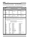
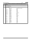
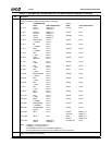
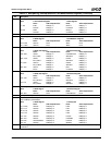
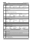
Table 4-3. WATCHDOG Registers
Bit Description
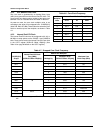
Offset 00h-01h WATCHDOG Timeout Register - WDTO (R/W) Reset Value: 0000h
This register specifies the programmed WATCHDOG timeout period.
15:0 Programmed timeout period.
Offset 02h-03h WATCHDOG Configuration Register - WDCNFG (R/W) Reset Value: 0000h
This register selects the signal to be generated when the timer reaches 0, whether or not to disable the 32 KHz input clock during low
power states, and the prescaler value of the clock input.
15:9 Reserved. Write as read.
8 WD32KPD (WATCHDOG 32 KHz Power Down).
0: 32 KHz clock is enabled.
1: 32 KHz clock is disabled, when the GX1 module asserts its internal SUSPA# signal.
This bit is cleared to 0, when POR# is asserted or when the GX1 module de-asserts its internal SUSPA# signal (i.e., on
SUSPA# rising edge). See Section 4.3.2.1 "Usage Hints" on page 84.
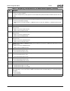
7:6 WDTYPE2 (WATCHDOG Event Type 2).
00: No action
01: Interrupt
10: SMI
11: System reset
This field is reset to 0 when POR# is asserted. Other system resets do not affect this field.
5:4 WDTYPE1 (WATCHDOG Event Type 1).
00: No action
01: Interrupt
10: SMI
11: System reset
This field is reset to 0 when POR# is asserted. Other system resets do not affect this field.
3:0 WDPRES (WATCHDOG Timer Prescaler). Divide 32 KHz by:
0000: 1 0100: 16 1000: 256 1100: 4096
0001: 2 0101: 32 1001: 512 1101: 8192
0010: 4 0110: 64 1010: 1024 1110: Reserved
0011: 8 0111: 128 1011: 2048 1111: Reserved
Offset 04h WATCHDOG Status Register - WDSTS (R/WC) Reset Value: 00h
This register contains WATCHDOG status information.
7:4 Reserved. Write as read.
3 WDRST (WATCHDOG Reset Asserted) (Read Only). This bit is set to 1 when WATCHDOG Reset is asserted. It is set to
0 when POR# is asserted, or when the WDOVF bit is set to 0.
2 WDSMI (WATCHDOG SMI Asserted.) (Read Only). This bit is set to 1 when WATCHDOG SMI is asserted. It is set to 0
when POR# is asserted, or when the WDOVF bit is set to 0.