


AMD Geode™ SC2200 Processor Data Book 403
Electrical Specifications
32580B
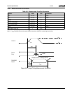
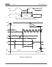
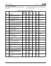
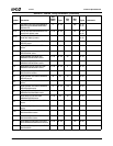
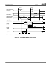
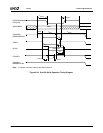
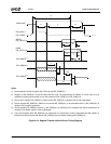
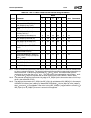
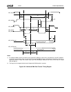
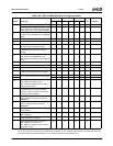
Table 9-25. IDE Register Transfer to/from Device Timing Parameters
Symbol Parameter
Mode
Unit Comments01235
t
0
Cycle time (min) 600 383 240 180 120 ns Note 1
t
1
Address valid to IDE_IOR[0:1]#/
IDE_IOW[0:1]# setup (min)
70 50 30 30 25 ns
t
2
IDE_IOR[0:1]#/IDE_IOW[0:1]# pulse
width 8-bit (min)
290 290 290 80 70 ns Note 1
t
2i
IDE_IOR[0:1]#/IDE_IOW[0:1]#
recovery time (min)
- - - 70 25 ns Note 1
t
3
IDE_IOW[0:1]# data setup (min) 6045303020ns
t
4
IDE_IOW[0:1]# data hold (min) 30 20 15 10 10 ns
t
5
IDE_IOR[0:1]# data setup (min) 5035202020ns
t
6
IDE_IOR[0:1]# data hold (min) 55555ns
t
6Z
IDE_IOR[0:1]# data TRI-STATE
(max)
30 30 30 30 30 ns Note 2
t
9
IDE_IOR[0:1]#/IDE_IOW[0:1]# to
address valid hold (min)
20 15 10 10 10 ns
t
RD
Read data valid to IDE_IORDY[0:1]
active (if IDE_IORDY[0:1] initially low
after t
A
(min)
00000ns
t
A
IDE_IORDY[0:1] setup time 35 35 35 35 35 ns Note 3
t
B
IDE_IORDY[0:1] pulse width (max) 1250 1250 1250 1250 1250 ns
t
C
IDE_IORDY[0:1] assertion to release
(max)
55555ns
Note 1. t
0
is the minimum total cycle time, t
2
is the minimum command active time, and t
2i
is the minimum command recov-
ery time or command inactive time. The actual cycle time equals the sum of the command active time and the com-
mand inactive time. The three timing requirements of t
0
, t
2
, and t
2i
are met. The minimum total cycle time
requirements is greater than the sum of t
2
and t
2i
. (This means that a host implementation can lengthen t
2
and/or
t
2i
to ensure that t
0
is equal to or greater than the value reported in the device’s IDENTIFY DEVICE data.)
Note 2. This parameter specifies the time from the rising edge of IDE_IOR[0:1]# to the time that the data bus is no longer
driven by the device (TRI-STATE).
Note 3. The delay from the activation of IDE_IOR[0:1]# or IDE_IOW[0:1]# until the state of IDE_IORDY[0,1] is first sampled.
If IDE_IORDY[0:1] is inactive, then the host waits until IDE_IORDY[0:1] is active before the PIO cycle is completed.
If the device is not driving IDE_IORDY[0:1] negated after activation (t
A
) of IDE_IOR[0:1]# or IDE_IOW[0:1]#, then
t
5
is met and t
RD
is not applicable. If the device is driving IDE_IORDY[0:1] negated after activation (t
A
) of
IDE_IOR[0:1]# or IDE_IOW[0:1]#, then t
RD
is met and t
5
is not applicable.