AMD Geode™ SC2200 Processor Data Book 351
Video Processor Module - Video Processor Registers - Function 4
32580B
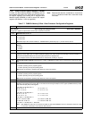
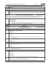
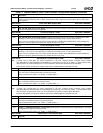
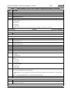
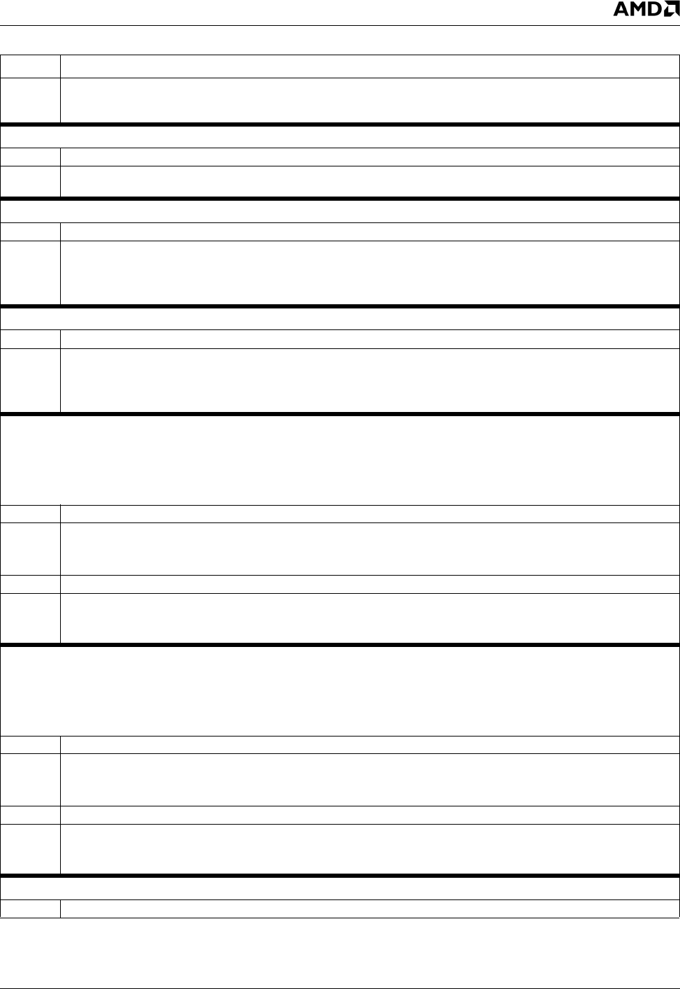
23:0 CUR_COLOR_KEY (Cursor Color Key). Specifies the 24-bit RGB value of the cursor color key. The incoming graphics
stream is compared with this value. If a match is detected, the pixel is replaced by a 24-bit value from one of the Cursor
Color registers.
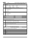
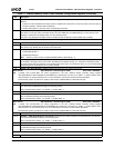
Offset 54h-57h Cursor Color Mask Register (R/W) Reset Value: 00000000h
31:24 Reserved.
23:0 CUR_COLOR_MASK (Cursor Color Mask). This mask is a 24-bit value. Zeroes in the mask cause the corresponding bits
in the incoming graphics stream to be ignored.
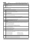
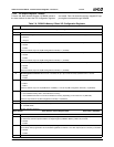
Offset 58h-5Bh Cursor Color Register 1 (R/W) Reset Value: 00000000h
31:24 Reserved.
23:0 CUR_COLOR_REG1 (Cursor Color Register 1). Specifies a 24-bit cursor color value. This is an RGB value (for RGB
blending) or a YUV value (for YUV blending). In interlaced YUV blending mode, Y/2 value should be used.
This is one of two possible cursor color values. The COLOR_REG_OFFSET bits (F4BAR0+Memory Offset 50h[28:24])
determine a bit of the graphics data that if even, selects this color to be used.
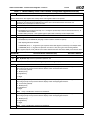
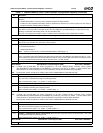
Offset 5Ch-5Fh Cursor Color Register 2 (R/W) Reset Value: 00000000h
31:24 Reserved.
23:0 CUR_COLOR_REG2 (Cursor Color Register 2). Specifies a 24-bit cursor color value. This is an RGB value (for RGB
blending) or a YUV value (for YUV blending). In interlaced YUV blending mode, Y/2 value should be used.
This is one of two possible cursor color values. The COLOR_REG_OFFSET bits (F4BAR0+Memory Offset 50h[28:24])
determine a bit of the graphics data that if even, selects this color to be used.
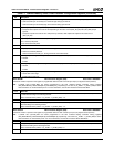
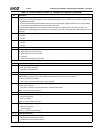
Offset 60h-63h Alpha Window 1 X Position Register (R/W) Reset Value: 00000000h
Note: H_TOTAL and H_SYNC_END are values programmed in the GX1 module’s Display Controller Timing registers
(GX_BASE+Memory Offset 8330h[26:19] and 8338h[10:3], respectively). The value of (H_TOTAL – H_SYNC_END) is some-
times referred to as “horizontal back porch”. For more information, see the GX1 Processor Series Data Book.
Desired screen position should not be outside a video window (F4BAR0+Memory Offset 08h and 0Ch).
31:27 Reserved.
26:16 ALPHA1_X_END (Alpha Window 1 Horizontal End). Determines the horizontal end position of Alpha Window 1 (not inclu-
sive). This value is calculated according to the following formula:
Value = Desired screen position + (H_TOTAL – H_SYNC_END) – 1.
15:11 Reserved.
10:0 ALPHA1_X_START (Alpha Window 1 Horizontal Start). Determines the horizontal start position of Alpha Window 1. This
value is calculated according to the following formula:
Value = Desired screen position + (H_TOTAL – H_SYNC_END) – 2.
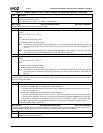
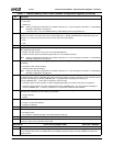
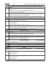
Offset 64h-67h Alpha Window 1 Y Position Register (R/W) Reset Value: 00000000h
Note: V_TOTAL and V_SYNC_END are values programmed in the GX1 module’s Display Controller Timing registers
(GX_BASE+Memory Offset 8340h[26:16] and 8348h[26:16], respectively). The value of (V_TOTAL – V_SYNC_END) is some-
times referred to as “vertical back porch”. For more information, see the GX1 Processor Series Data Book.
Desired screen position should not be outside a video window (F4BAR0+Memory Offset 08h and 0Ch).
31:27 Reserved.
26:16 ALPHA1_Y_END (Alpha Window 1 Vertical End). Determines the vertical end position of Alpha Window 1 (not inclusive).
This value is calculated according to the following formula:
Value = Desired screen position + (V_TOTAL – V_SYNC_END) + 2.
15:11 Reserved.
10:0
ALPHA1_Y_START (Alpha Window 1 Vertical Start). Determines the vertical start position of Alpha Window 1. This value
is calculated according to the following formula:
Value = Desired screen position + (V_TOTAL – V_SYNC_END) + 1.
Offset 68h-6Bh Alpha Window 1 Color Register (R/W) Reset Value: 00000000h
31:25 Reserved.
Table 7-7. F4BAR0+Memory Offset: Video Processor Configuration Registers (Continued)
Bit Description


