


114 AMD Geode™ SC2200 Processor Data Book
SuperI/O Module
32580B
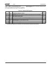
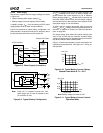
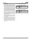
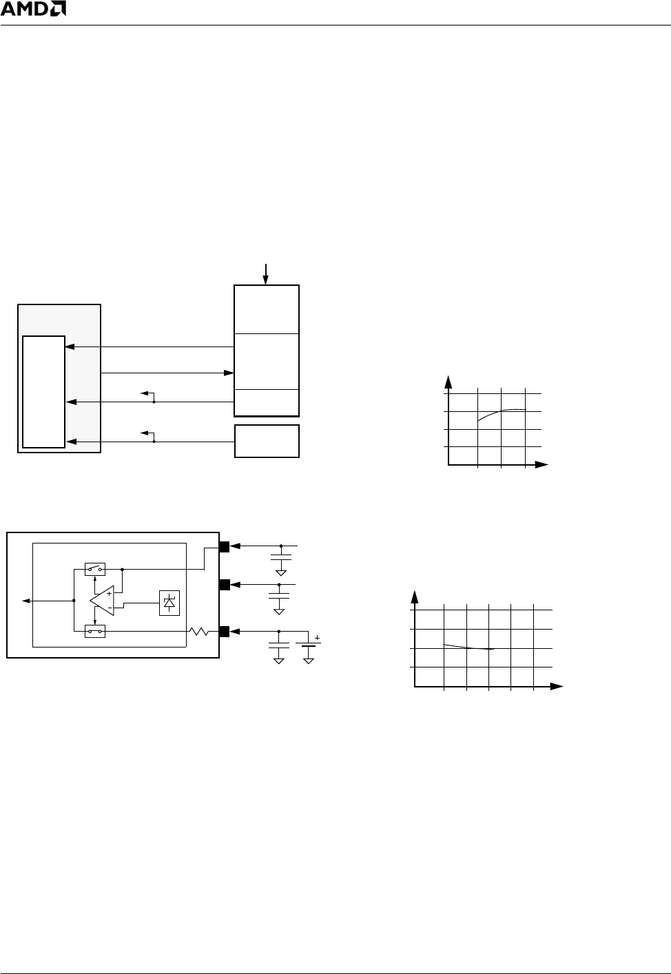
5.5.2.6 Power Supply
The device is supplied from two supply voltages, as shown
in Figure 5-8:
• System standby power supply voltage, V
SB
• Backup voltage, from low capacity Lithium battery
A standby voltage, V
SB
, from the external AC/DC power
supply powers the RTC under normal conditions.
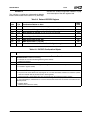
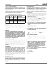
Figure 5-9 represents a typical battery configuration. No
external diode is required to meet the UL standard, due to
the internal switch and internal serial resistor R
UL
.
Figure 5-8. Power Supply Connections
Figure 5-9. Typical Battery Configuration
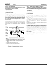
The RTC is supplied from one of two power supplies, V
SB
or V
BAT
, according to their levels. An internal voltage com-
parator delivers the control signals to a pair of switches.
Battery backup voltage V
BAT
maintains the correct time and
saves the CMOS memory when the V
SB
voltage is absent,
due to power failure or disconnection of the external AC/DC
input power supply or V
SB
main battery.
To assure that the module uses power from V
SB
and not
from V
BAT
, the V
SB
voltage should be maintained above its
minimum, as detailed in Section 9.0 "Electrical Specifica-
tions" on page 369.
The actual voltage point where the module switches from
V
BAT
to V
SB
is lower than the minimum workable battery
voltage, but high enough to guarantee the correct function-
ality of the oscillator and the CMOS RAM.
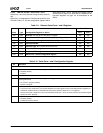
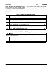
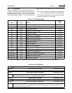
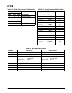
Figure 5-10 shows typical battery current consumption dur-
ing battery-backed operation, and Figure 5-11 during nor-
mal operation.
Figure 5-10. Typical Battery Current: Battery
Backed Power Mode @ T
C
= 25°C
Figure 5-11. Typical Battery Current: Normal
Operation Mode
RTC
Power
Backup
V
DIGITAL
V
SB
V
DIGITAL
V
SB
V
BAT
Battery
External AC Power
Supply
V
DIGITAL
Sense
V
SB
V
BAT
V
SB
PC0
V
BAT
ONCTL#
ONCTL#
ACPI Controller
V
BAT
0.1 μF
V
SB
V
SB
C
F
C
F
BT
1
0.1 μF
V
PP
R
UL
V
REF
RTC
Note: Place a 0.1 μF capacitor on each V
SB
, V
SBL
power supply pin as close as possible to the
pin, and also on V
BAT
.
V
SBL
C
F
0.1 μF
V
SBL
I
BAT
(μA)
10.0
7.5
5.0
2.5
2.4 3.0 3.6
V
BAT
(V)
I
BAT
(μA)
0.75
0.50
0.25
3.0 3.3 3.6
V
SB
Note: Battery voltage in this test is 3.0V.
(V)