


204 AMD Geode™ SC2200 Processor Data Book
Core Logic Module - Bridge, GPIO, and LPC Registers - Function 0
32580B
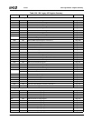
Index 48h-4Bh Reserved Reset Value: 00h
Index 4Ch-4Fh Top of System Memory (R/W) Reset Value: FFFFFFFFh
31:0 Top of System Memory. Highest address in system used to determine active decode for external PCI mastered memory
cycles.
If an external PCI master requests a memory address below the value programmed in this register, the cycle is transferred
from the external PCI bus interface to the Fast-PCI interface for servicing by the GX1 module.
Note: The four least significant bits must be set to 1100.
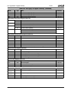
Index 50h PIT Control/ISA CLK Divider (R/W) Reset Value: 7Bh
7 PIT Software Reset.
0: Disable.
1: Enable.
6 PIT Counter 1.
0: Forces Counter 1 output (OUT1) to zero.
1: Allows Counter 1 output (OUT1) to pass to the Port 061h[4].
5 PIT Counter 1 Enable.
0: Sets GATE1 input low.
1: Sets GATE1 input high.
4 PIT Counter 0.
0: Forces Counter 0 output (OUT0) to zero.
1: Allows Counter 0 output (OUT0) to pass to IRQ0.
3 PIT Counter 0 Enable.
0: Sets GATE0 input low.
1: Sets GATE0 input high.
2:0 ISA Clock Divisor. Determines the divisor of the PCI clock used to make the ISA clock, which is typically programmed for
approximately 8 MHz:
000: Divide by 1 100: Divide by 5
001: Divide by 2 101: Divide by 6
010: Divide by 3 110: Divide by 7
011: Divide by 4 111: Divide by 8
If PCI clock = 25 MHz, use setting of 010 (divide by 3).
If PCI clock = 30 or 33 MHz, use a setting of 011 (divide by 4).
Index 51h ISA I/O Recovery Control Register (R/W) Reset Value: 40h
7:4 8-Bit I/O Recovery. These bits determine the number of ISA bus clocks between back-to-back 8-bit I/O read cycles. This
count is in addition to a preset one-clock delay built into the controller.
0000: 1 PCI clock
0001: 2 PCI clocks
:::
:::
:::
1111: 16 PCI clocks
3:0 16-Bit I/O Recovery. These bits determine the number of ISA bus clocks between back-to-back 16-bit I/O cycles. This
count is in addition to a preset one-clock delay built into the controller.
0000: 1 PCI clock
0001: 2 PCI clocks
:::
:::
:::
1111: 16 PCI clocks
Table 6-29. F0: PCI Header/Bridge Configuration Registers for GPIO and LPC Support (Continued)
Bit Description