


AMD Geode™ SC2200 Processor Data Book 101
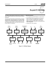
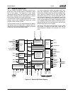
SuperI/O Module
32580B
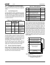
Table 5-3 provides the bit definitions for the Standard Con-
figuration registers.
• All reserved bits return 0 on reads, except where noted
otherwise. They must not be modified as such modifica-
tion may cause unpredictable results. Use read-modify-
write to prevent the values of reserved bits from being
changed during write.
• Write only registers should not use read-modify-write
during updates.
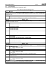
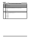
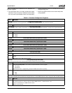
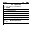
Table 5-3. Standard Configuration Registers
Bit Description
Index 07h Logical Device Number (R/W)
This register selects the current logical device. See Table 5-2 for valid numbers. All other values are reserved.
7:0 Logical Device number.
Index 20h-2Fh SIO Configuration (R/W)
SIO configuration and ID registers. See Section 5.4.1 "SIO Control and Configuration Registers" on page 103 for register/bit details.
Index 30h Activate (R/W)
7:1 Reserved.
0 Logical Device Activation Control.
0: Disable.
1: Enable.
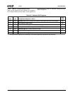
Index 60h I/O Port Base Address Bits [15:8] Descriptor 0 (R/W)
7:0 Descriptor 0 A[15:8]. Selects I/O lower limit address bits [15:8] for I/O Descriptor 0.
Index 61h I/O Port Base Address Bits [7:0] Descriptor 0 (R/W)
7:0 Descriptor 0 A[7:0]. Selects I/O lower limit address bits [7:0] for I/O Descriptor 0.
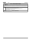
Index 62h I/O Port Base Address Bits [15:8] Descriptor 1 (R/W)
7:0 Descriptor 1 A[15:8]. Selects I/O lower limit address bits [15:8] for I/O Descriptor 1.
Index 63h I/O Port Base Address Bits [7:0] Descriptor 1 (R/W)
7:0 Descriptor 1 A[7:0]. Selects I/O lower limit address bits [7:0] for I/O Descriptor 1.
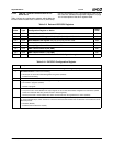
Index 70h Interrupt Number (R/W)
7:4 Reserved.
3:0 Interrupt Number. These bits select the interrupt number. A value of 1 selects IRQ1, a value of 2 selects IRQ2, etc. (up to
IRQ12).
Note: IRQ0 is not a valid interrupt selection.
Index 71h Interrupt Request Type Select (R/W)
Selects the type and level of the interrupt request number selected in the previous register.
7:2 Reserved.
1 Interrupt Level Requested. Level of interrupt request selected in previous register.
0: Low polarity.
1: High polarity.
This bit must be set to 1 (high polarity), except for IRQ8#, that must be low polarity.
0 Interrupt Type Requested. Type of interrupt request selected in previous register.
0: Edge.
1: Level.
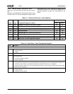
Index 74h DMA Channel Select 0 (R/W)
Selects selected DMA channel for DMA 0 of the logical device (0 - the first DMA channel in case of using more than one DMA channel).
7:3 Reserved.
2:0 DMA 0 Channel Select. This bit field selects the DMA channel for DMA 0.
The valid choices are 0-3, where a value of 0 selects DMA channel 0, 1 selects channel 1, etc.
A value of 4 indicates that no DMA channel is active.
Values 5-7 are reserved.