


AMD Geode™ SC2200 Processor Data Book 19
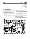
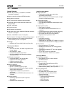
Architecture Overview
32580B
5 2CLKADDR (Two Clock Address Setup). Assert memory address for one extra clock before CS# is asserted.
0: Disable.
1: Enable.
This can be used to compensate for address setup at high frequencies and/or high loads.
4 RFSHTST (Test Refresh). This bit, when set high, generates a refresh request. This bit is only used for testing purposes.
3 XBUSARB (X-Bus Round Robin). When round robin is enabled, processor, graphics pipeline, and low priority display con-
troller requests are arbitrated at the same priority level. When disabled, processor requests are arbitrated at a higher priority
level. High priority Display Controller requests always have the highest arbitration priority.
0: Disable.
1: Enable round robin.
2 SMM_MAP (SMM Region Mapping). Maps the SMM memory region at GX_BASE+400000 to physical address A0000 to
BFFFF in SDRAM.
0: Disable.
1: Enable.
1 RSVD (Reserved). Write as 0.
0 SDRAMPRG (Program SDRAM). When this bit is set, the memory controller will program the SDRAM MRS register using
LTMODE in MC_SYNC_TIM1.
This bit must transition from zero (written to zero) to one (written to one) in order to program the SDRAM devices.
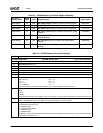
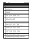
GX_BASE+8404h-8407h MC_MEM_CNTRL2 (R/W) Reset Value: 00000801h
31:14 RSVD (Reserved). Write as 0.
13:12 SDCLKCTL (SDCLK High Drive/Slew Control). Controls the high drive and slew rate of SDCLK[3:0] and SDCLK_OUT.
11 is strongest, 00 is weakest.
11 RSVD (Reserved). Write as 0.
10 SDCLKOMSK# (Enable SDCLK_OUT). Turns on the output.
0: Enable.
1: Disable.
9 SDCLK3MSK# (Enable SDCLK3). Turns on the output.
0: Enable.
1: Disable.
8 SDCLK2MSK# (Enable SDCLK2). Turns on the output.
0: Enable.
1: Disable.
7 SDCLK1MSK# (Enable SDCLK1). Turns on the output.
0: Enable.
1: Disable.
6 SDCLK0MSK# (Enable SDCLK0). Turns on the output.
0: Enable.
1: Disable.
5:3 SHFTSDCLK (Shift SDCLK). This function allows shifting SDCLK to meet SDRAM setup and hold time requirements. The
shift function will not take effect until the SDCLKSTRT bit (bit 17 of MC_MEM_CNTRL1) transitions from 0 to 1:
000: No shift 100: Shift 2 core clocks
001: Shift 0.5 core clock 101: Shift 2.5 core clocks
010: Shift 1 core clock 110: Shift 3 core clocks
011: Shift 1.5 core clock 111: Reserved
2 RSVD (Reserved). Write as 0.
1 RD (Read Data Phase). Selects if read data is latched one or two core clock after the rising edge of SDCLK.
0: 1 Core clock.
1: 2 Core clocks.
0 FSTRDMSK (Fast Read Mask). Do not allow core reads to bypass the request FIFO.
0: Disable.
1: Enable.
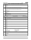
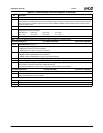
Table 2-2. SC2200 Memory Controller Registers (Continued)
Bit Description