


AMD Geode™ SC2200 Processor Data Book 203
Core Logic Module - Bridge, GPIO, and LPC Registers - Function 0
32580B
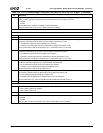
2 IDE Reset. Reset IDE bus.
0: Disable.
1: Enable (drive IDE_RST# low).
Write 0 to clear. This bit is level-sensitive and must be cleared after the reset is enabled.
Note: When X-Bus Warm Start is enabled (bit 0 = 1) or during POR#, IDE_RST# is put into TRI-STATE mode. To prop-
erly reset the IDE bus, after POR# the boot code must cause IDE_RST# to activate.
1 PCI Reset. Reset PCI bus.
0: Disable.
1: Enable.
When this bit is set to 1, the Core Logic module output signal PCIRST# is asserted and all devices on the PCI bus (including
PCIUSB) are reset. No other function within the Core Logic module is affected by this bit.
Write 0 to clear this bit. This bit is level-sensitive and must be cleared after the reset is enabled.
0 X-Bus Warm Start. Writing and reading this bit each have different meanings.
When reading this bit, it indicates whether or not a warm start occurred since power-up:
0: A warm start occurred.
1: No warm start has occurred.
When writing this bit, it can be used to trigger a system-wide reset:
0: No effect.
1: Execute system-wide reset (used only for clock configuration at power-up).
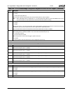
Index 45h Reserved Reset Value: 00h
Index 46h PCI Functions Enable Register (R/W) Reset Value: FEh
7:6 Reserved. Resets to 11.
5 F5 (PCI Function 5). When asserted (set to 1), enables the register space designated as F5.
This bit must always be set to 1. (Default)
4 F4 (PCI Function 4). When asserted (set to 1), enables the register space designated as F4.
This bit must always be set to 1. (Default)
3 F3 (PCI Function 3). When asserted (set to 1), enables the register space designated as F3.
This bit must always be set to 1. (Default)
2 F2 (PCI Function 2). When asserted (set to 1), enables the register space designated as F2.
This bit must always be set to 1. (Default)
1 F1 (PCI Function 1). When asserted (set to 1), enables the register space designated as F1.
This bit must always be set to 1. (Default)
0 Reserved. Must be set to 0.
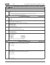
Index 47h Miscellaneous Enable Register (R/W) Reset Value: 00h
7:3 Reserved. Must be set to 0.
2 F0BAR1 (PCI Function 0, Base Address Register 1). F0BAR1, pointer to I/O mapped LPC configuration registers.
0: Disable.
1: Enable.
1 F0BAR0 (PCI Function 0, Base Address Register 0). F0BAR0, pointer to I/O mapped GPIO configuration registers.
0: Disable.
1: Enable.
0 Reserved. Must be set to 0.
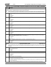
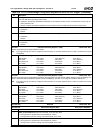
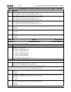
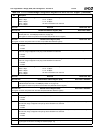
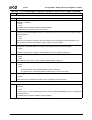
Table 6-29. F0: PCI Header/Bridge Configuration Registers for GPIO and LPC Support (Continued)
Bit Description