AMD Geode™ SC2200 Processor Data Book 125
SuperI/O Module
32580B
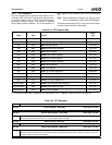
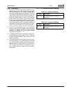
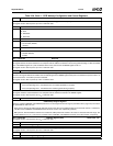
Table 5-30. Bank 1 - CEIR Wakeup Configuration and Control Registers
Bit Description
Bank 1, Offset 03h CEIR Wakeup Control Register - IRWCR (R/W) Reset Value: 00h
This register is set to 00h on power-up of V
PP
or software reset.
7:6 Reserved.
5:4 CEIR Protocol Select.
00: RC5.
01: NEC/RCA.
1x: Reserved.
3 Reserved.
2 Invert IRRX Input.
0: Not inverted. (Default)
1: Inverted.
1 Reserved.
0 CEIR Enable.
0: Disable. (Default)
1: Enable.
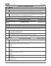
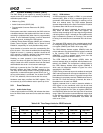
Bank 1, Offset 04h Reserved
Bank 1, Offset 05h CEIR Wakeup Address Register - IRWAD (R/W) Reset Value: 00h
This register defines the station address to be compared with the address contained in the incoming CEIR message. If CEIR is enabled
(bit 0 of the IRWCR register is 1) and an address match occurs, then bit 5 of the WKSR register is set to 1.
This register is set to 00h on power-up of V
PP
or software reset.
7:0 CEIR Wakeup Address.
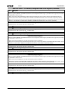
Bank 1, Offset 06h CEIR Wakeup Mask Register - IRWAM (R/W) Reset Value: E0h
Each bit in this register determines whether the corresponding bit in the IRWAD register takes part in the address comparison. Bits 5, 6,
and 7 must be set to 1 if the RC-5 protocol is selected.
This register is set to E0h on power-up of V
PP
or software reset.
7:0 CEIR Wakeup Address Mask.
• If the corresponding bit is 0, the address bit is not masked (enabled for compare).
• If the corresponding bit is 1, the address bit is masked (ignored during compare).
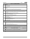
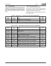
Bank 1, Offset 07h CEIR Address Shift Register - ADSR (RO) Reset Value: 00h
This register holds the received address to be compared with the address contained in the IRWAD register.
This register is set to 00h on power-up of V
PP
or software reset.
7:0 CEIR Address.
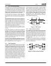
CEIR Wakeup Range 0 Registers
These two registers (IRWTR0L and IRWTR0H) define the low and high limits of time range 0 (see Table 5-26 on page 123). The values
are represented in units of 0.1 ms.
• RC-5 protocol: The bit cell width must fall within this range for the cell to be considered valid. The nominal cell width is 1.778 msec for
a 36 KHz carrier. IRWTR0L and IRWTR0H should be set to 10h and 14h, respectively. (Default)
• NEC protocol: The time distance between two consecutive CEIR pulses that encodes a bit value of 0 must fall within this range. The
nominal distance for a 0 is 1.125 msec for a 38 KHz carrier. IRWTR0L and IRWTR0H should be set to 09h and 0Dh, respectively.
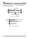
Bank 1, Offset 08h IRWTR0L Register (R/W) Reset Value: 10h
This register is set to 10h on power-up of V
PP
or software reset.
7:5 Reserved.
4:0 CEIR Pulse Change, Range 0, Low Limit.
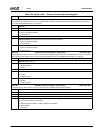
Bank 1, Offset 09h IRWTR0H Register (R/W) Reset Value: 14h
This register is set to 14h on power-up of V
PP
or software reset.
7:5 Reserved.
4:0 CEIR Pulse Change, Range 0, High Limit.


