


AMD Geode™ SC2200 Processor Data Book 111
SuperI/O Module
32580B
5.5 Real-Time Clock (RTC)
The RTC provides timekeeping and calendar management
capabilities. The RTC uses a 32.768 KHz signal as the
basic clock for timekeeping. It also includes 242 bytes of
battery-backed RAM for general-purpose use.
The RTC provides the following functions:
• Accurate timekeeping and calendar management
• Alarm at a predetermined time and/or date
• Three programmable interrupt sources
• Valid timekeeping during power-down, by utilizing
external battery backup
• 242 bytes of battery-backed RAM
• RAM lock schemes to protect its content
• Internal oscillator circuit (the crystal itself is off-chip), or
external clock supply for the 32.768 KHz clock
• A century counter
• PnP support:
— Relocatable Index and Data registers
— Module access enable/disable option
— Host interrupt enable/disable option
• Additional low-power features such as:
— Automatic switching from battery to V
SB
— Internal power monitoring on the VRT bit
— Oscillator disabling to save battery during storage
• Software compatible with the DS1287 and MC146818
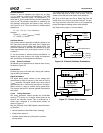
5.5.1 Bus Interface
The RTC function is initially mapped to the default SuperI/O
locations at Indexes 70h to 73h (two Index/Data pairs).
These locations may be reassigned, in compliance with
Plug and Play requirements.
5.5.2 RTC Clock Generation
The RTC uses a 32.768 KHz clock signal as the basic
clock for timekeeping. The 32.768 KHz clock can be sup-
plied by the internal oscillator circuit, or by an external
oscillator (see Section 5.5.2.2 "External Oscillator" on page
112).
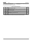
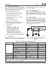
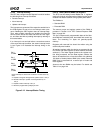
5.5.2.1 Internal Oscillator
The internal oscillator employs an external crystal con-
nected to the on-chip amplifier. The on-chip amplifier is
accessible on the X32I input and X32O output. See Figure
5-5 for the recommended external circuit and Table 5-17 for
a listing of the circuit components. The oscillator may be
disabled in certain conditions. See Section 5.5.2.8 "Oscilla-
tor Activity" on page 115 for more details.
Figure 5-5. Recommended Oscillator External
Circuitry
V
BAT
C
F
Internal
External
R
2
X32I
X32O
C
1
C
2
R
1
Y
To other
modules
Battery
B
1
C
F
= 0.1 μF
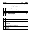
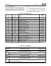
Table 5-17. Crystal Oscillator Circuit Components
Component Parameters Values Tolerance
Crystal Resonance Frequency 32.768 KHz Parallel mode User-defined
Type N-cut or XY-bar
Serial Resistance 40 KΩ Max
Quality Factor, Q 35000 Min
Shunt Capacitance 2 pF Max
Load Capacitance, C
L
9-13 pF
Temperature Coefficient User-defined
Resistor R
1
Resistance 20 MΩ 5%
Resistor R
2
Resistance 120 KΩ 5%
Capacitor C
1
Capacitance 3 to 10 pF (Note) 5%
Capacitor C
2
Capacitance 3 to 10 pF (Note) 5%
Note: When voltage is applied to the oscillator it may not start to oscillate immediately due to the balanced external circuit. In general
this is not a problem because the oscillator runs all the time (whether system is on or off). In systems where this is not the case, C1 and
C2 should be different by 50% to assure an unbalanced circuit