


AMD Geode™ SC2200 Processor Data Book 69
Signal Definitions
32580B
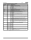
PWRBTN# AH5 I Power Button. Input used by the power management
logic to monitor external system events, most typically a
system on/off button or switch.
The signal has an internal pull-up of 100 KΩ, a Schmitt-
trigger input buffer and debounce protection of at least 16
ms.
ACPI is non-functional and all ACPI outputs are unde-
fined when the power-up sequence does not include
using the power button. SUSP# is an internal signal gen-
erated from the ACPI block. Without an ACPI reset,
SUSP# can be permanently asserted. If the USE_SUSP
bit in CCR2 of GX1 module is enabled (Index C2h[7] = 1),
the CPU will stop.
If ACPI functionality is desired, or the situation described
above avoided, the power button must be toggled. This
can be done externally or internally. GPIO63 is internally
connected to PWRBTN#. To toggle the power button with
software, GPIO63 must be programmed as an output
using the normal GPIO programming protocol (see Sec-
tion 6.4.1.1 "GPIO Support Registers" on page 233).
GPIO63 must be pulsed low for at least 16 ms and not
more than 4 sec.
Asserting POR# has no effect on ACPI. If POR# is
asserted and ACPI was active prior to POR#, then ACPI
will remain active after POR#. Therefore, BIOS must
ensure that ACPI is inactive before GPIO63 is pulsed
low.
---
PWRCNT1 AK6 O Suspend Power Plane Control 1 and 2. Control signal
asserted during power management Suspend states.
These signals are open-drain outputs.
---
PWRCNT2 AL7 O ---
THRM# AK4 I Thermal Event. Active low signal generated by external
hardware indicating that the system temperature is too
high.
---
3.4.15 Power Management Interface Signals (Continued)
Signal Name Ball No. Type Description Mux