


ColorQube™ 9201/9202/9203 Security
System Administrator Guide 8-5
6. Select [IP Filtering] in the directory tree.
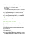
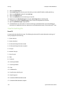
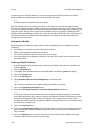
Defining IP Filtering with the Define IP Filter Rule dialog
7. Click on the [Add] button to display the Add IP Filter Rule page.
8. From the [Protocol] drop-down list, select the protocol (All, TCP, UDP or ICMP) that the rule will apply to.
9. From the [Action] drop-down list, select how you wish IP Filtering to handle the incoming packet.
10. From the [Move This Rule To] drop-down list, select either End of List or Beginning of List for the
location of this rule. Note that rule order is important in IP Filtering because rules can negate each other
if placed in an incorrect order.
11. Enter the [Source IP Address] to which this rule will apply.
12. Enter a number for the [Source IP Mask] to which this rule will apply. The allowable range of 0 to 32
corresponds to the 32 bit binary number comprising IP addresses. A number of 8, for example,
represents a Class A address (mask of 255, 0, 0, 0). The number 16 represents a Class B address (mask of
255, 255, 0, 0). The number 24 represents a Class C address (mask of 255, 255, 255, 0).
13. [Source Port]: This selection is only available when the Protocol has been set to TCP. Enter the
originating port (if applicable) that the rule has been created to handle. If the incoming packet did not
originate from this source port, the rule will not be applied.
14. [Destination Port]: This selection is only available when the protocol is set to TCP or UDP. Enter the
destination port that the rule has been created to handle. If the incoming packet was not sent to this
port, the rule will not be applied.
15. [ICMP Message]: This selection is only available when the protocol is set to ICMP. Select which ICMP
Message the rule is meant to handle.
16. Click on the [Apply] button to accept the changes or on the [Cancel] button to exit the window without
saving changes.
Note
The settings are not applied until you restart the device.
Audit Log
Audit Log is a log that tracks access and attempted access to the server. With TCP/IP and HTTP-based
processes running on the server, exposure to access attacks, eavesdropping, file tampering, service disruption,
and identity (password) theft is significantly increased. The Audit Log, regularly reviewed by the System
Administrator, often with the aid of third party analyzing tools, helps to assess attempted server security
breaches, identify actual breaches, and prevent future breaches. Access to the log’s data is protected by
enabling SSL (Secure Sockets Layer) protocols. The audit log, and its associated data protected by strong SSL
encryption, helps to meet the Controlled Access Protection (Class C2) criteria, set by the United States
Department of Defense. To enable this feature, perform the following steps.
IMPORTANT: Audit Log cannot be enabled until SSL (Secure Sockets Layer) is enabled on the device. To
enable SSL on a device, the device needs to have a Server Certificate. For instructions to set up a Server
Certificate, see Machine Digital Certificate Management on page 8-9.
1. At your Workstation, open the web browser and enter the IP address of the device in the Address bar,
and press [Enter].
2. Click the [Properties] tab.
3. If prompted, enter the Administrator User ID and Password. The default is [admin] and [1111].
4. Click on the [Login] button.