


118 System Configuration Commands
show port
Example
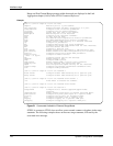
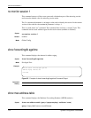
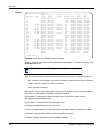
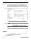
Figure 28 show port all Command Output Example
Interface—Valid unit, slot and port number separated by forward slashes.. This field only displays in the
show port all report.
Type—If not blank, this field indicates that this port is a special type of port. The possible values are:
Mon—Indicates a monitoring port. Look at the Port Monitoring screens to find out more information.
PC Mbr—Indicates a member of a LAG (port channel).
Probe—Indicates a probe port.
Admin Mode—The port administration state. The port must be enabled in order for it to be allowed into
the network. It is either enabled or disabled. The default is enabled.
Physical Mode—The desired port speed and duplex mode. In the S2410, all ports are set to
auto-negotiate speed and duplex mode.
Physical Status—Indicates the port speed and duplex mode.
Link Status—Indicates whether the Link is up or down.
Link Trap—Indicates whether or not to send a trap when link status changes. The default is enabled.
LACP Mode—Displays whether LACP is enabled or disabled on this port.
Flow Mode—Displays whetherflow control is enabled or disabled.
Force10 S2410 #show port all
Admin Physical Physical Link Link LACP Flow
Interface Type Mode Mode Status Status Trap Mode Mode
---------- ------ ------- ---------- ---------- ------ ------- ------- -------
0/1 Enable 10G Full Down Enable Enable Disable
0/2 Enable 10G Full Down Enable Enable Disable
0/3 Enable 10G Full Down Enable Enable Disable
0/4 Enable 10G Full Down Enable Enable Disable
0/5 PC Mbr Enable 10G Full 10G Full Up Enable Enable Disable
0/6 Enable 10G Full 10G Full Up Enable Enable Disable
0/7 Enable 10G Full 10G Full Up Enable Enable Disable
0/8 PC Mbr Enable 10G Full 10G Full Up Enable Enable Disable
0/9 PC Mbr Enable 10G Full 10G Full Up Enable Enable Disable
0/10 PC Mbr Enable 10G Full Down Enable Enable Disable
0/11 PC Mbr Enable 10G Full 10G Full Up Enable Enable Disable
0/12 PC Mbr Enable 10G Full 10G Full Up Enable Enable Disable
0/13 Disable 10G Full Down Enable Enable Disable
0/14 Enable 10G Full Down Enable Enable Disable
0/15 Enable 10G Full Down Enable Enable Disable
0/16 PC Mbr Enable 10G Full 10G Full Up Enable Enable Disable
0/17 PC Mbr Enable 10G Full 10G Full Up Enable Enable Disable
0/18 PC Mbr Enable 10G Full 10G Full Up Enable Enable Disable
0/19 PC Mbr Enable 10G Full 10G Full Up Enable Enable Disable
0/20 PC Mbr Enable 10G Full 10G Full Up Enable Enable Disable
0/21 PC Mbr Enable 10G Full 10G Full Up Enable Enable Disable
0/22 PC Mbr Enable 10G Full 10G Full Up Enable Enable Disable
0/23 PC Mbr Enable 10G Full 10G Full Up Enable Enable Disable
0/24 Disable 10G Full Down Enable Enable Disable
1/1 Enable Up Enable N/A Enable
1/2 Enable Up Enable N/A Enable
Force10 S2410 #
Note: Port IDs 1/1 and 1/2 in Figure 28 are LAGs.