


Removal and Installation
8-38
HP DesignJet 5000 Series Printers Service Manual
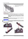
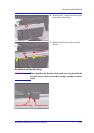
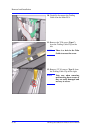
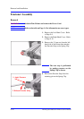
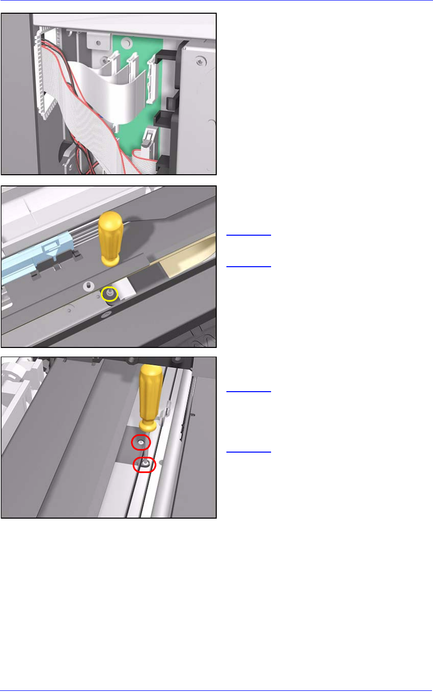
10. Carefully disconnect the Trailing
Cable from the Main PCA.
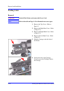
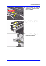
11. Remove the T-20 screw (Type C)
from the Trailing Cable Clip on the
left.
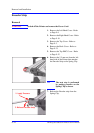
NOTE There is a hole in the Tube
Guide to access the screw.
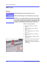
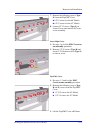
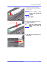
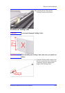
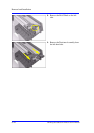
12. Remove 2 T-10 screws (Type I) from
the Trailing Cable Clip on the right.
NOTE Take care when removing
and inserting these screws as
they are easily damaged and
not easy to access.