


Removal and Installation
8-77
HP DesignJet 5000 Series Printers Service Manual
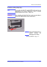
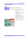
Electronics Module Cover
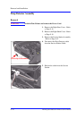
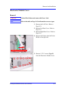
Removal
WARNING Switch off the Printer and remove the Power Cord.
NOTE Refer to the table on Page 8-4 for information on screw types.
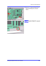
1. Remove the LAN Card - Refer to
Page 8-74.
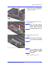
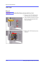
2. Remove Left Rear Cover - Refer to
Page 8-15.
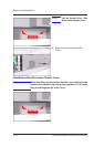
3. Remove Right Rear Cover - Refer to
Page 8-16.
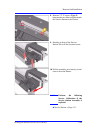
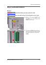
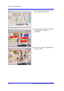
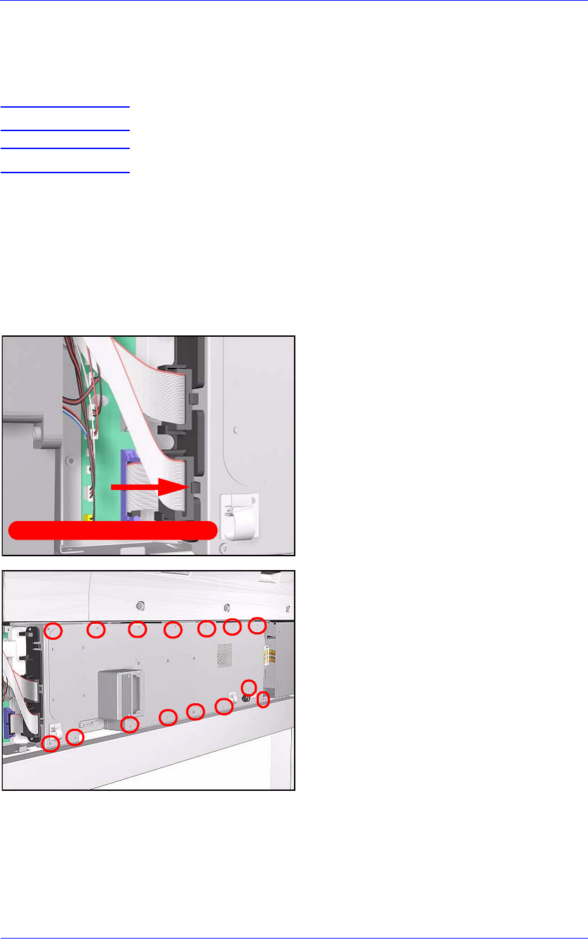
4. Remove the Ferrites from the Ferrite
Holder on the right side.
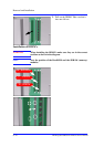
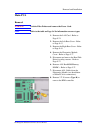
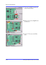
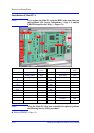
5. Remove 15 T-15 screws (Type B)
from the Electronics Module Cover.
Push clip to release Ferrite