


103
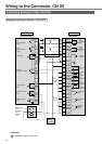
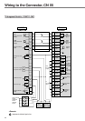
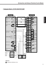
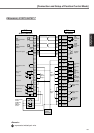
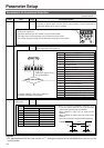
[Connection and Setup of Position Control Mode]
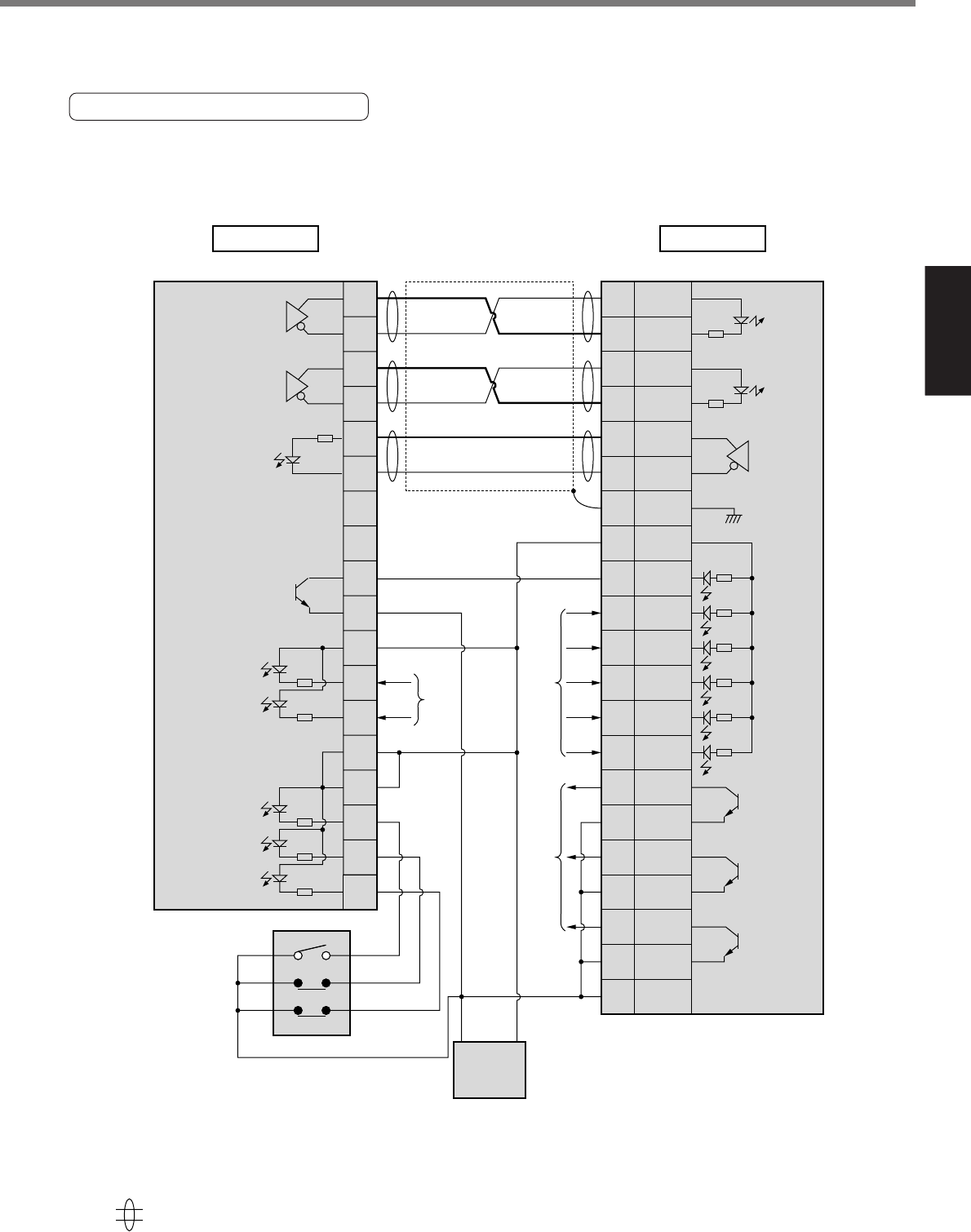
Connection and Setup of
Position Control Mode
Mitsubishi, A1SD75/AD75P1
220Ω
220Ω
4.7
k
Ω
4.7
k
Ω
4.7
k
Ω
4.7
k
Ω
4.7
k
Ω
4.7
k
Ω
CW
pulse command
output
CCW
pulse command
output
Zero point signal
Deviation counter
clear
In position
Common
Proximity signal
Upper limit
Lower limit
Drive unit
ready
CW
pulse
command
input
3
21
4
22
24
25
5
23
26
7
8
35
36
11
12
13
PULS1
PULS2
SIGN1
SIGN2
OZ+
OZ–
GND
COM+
CL
SRV-ON
GAIN
A-CLR
CCWL
CWL
S-RDY
+
S-RDY
–
ALM+
ALM–
COIN+
COIN–
COM–
3
4
5
6
23
24
13
7
30
29
27
31
9
8
35
34
37
36
39
38
41
CCW
pulse
command
input
Counter clear
input
Servo-ON
input
Servo-Ready
output
Servo-Alarm
output
Positioning
complete
output
Gain
switching
input
Alarm clear
input
CW
over-travel
inhibit input
CCW
over-travel
inhibit input
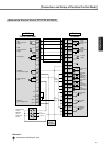
PLC
A1SD75/AD75P1
Driver
A4-series
Z-phase
output
from
PLC I/O
outpu
t
from
PLC I/O
outpu
t
to
PLC I/O
input
4.7
k
Ω
4.7
k
Ω
4.7
k
Ω
4.7
k
Ω
4.7
k
Ω
500Ω
Origin proximity
sensor
CW limit
sensor
CCW limit
sensor
GND + 24V
DC24V
Power supply
represents twisted pair wire.
<Remark>