


146
Parameter Setup
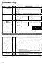
0B
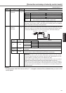
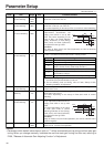
*
0 to 2
<1>
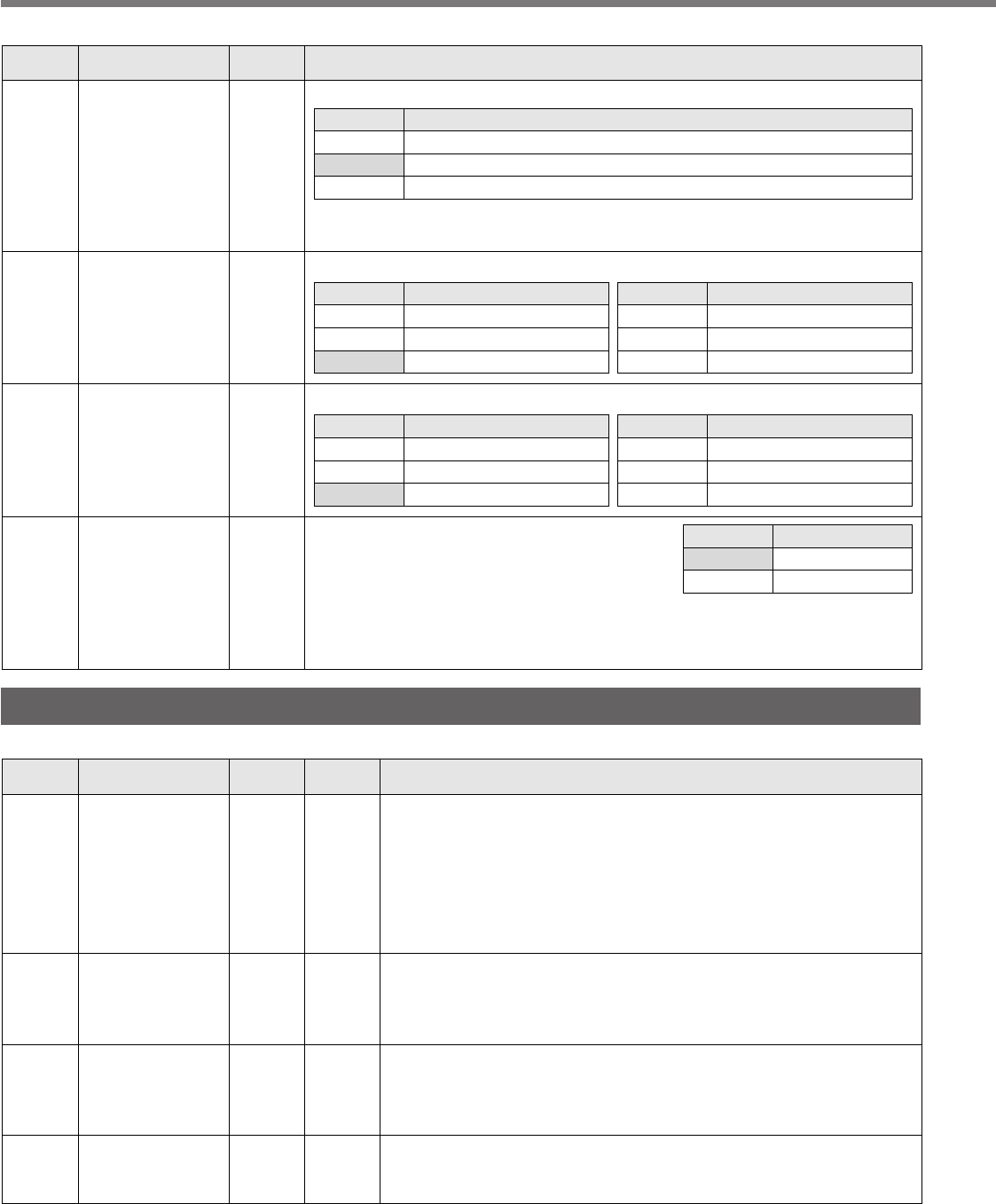
Setup of
absolute encoder
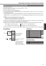
You can set up the using method of 17-bit absolute encoder.
<Caution>
This parameter will be invalidated when 5-wire, 2500P/r incremental encoder is used.
Setup value
0
<1>
2
Content
Use as an absolute encoder.
Use as an incremental encoder.
Use as an absolute encoder, but ignore the multi-turn counter over.
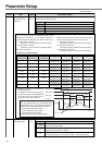
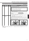
0C
*
0 to 5
<2>
Baud rate setup of
RS232
communication
You can set up the communication speed of RS232.
Setup value
0
1
<2>
Baud rate
2400bps
4800bps
9600bps
Setup value
3
4
5
Baud rate
19200bps
38400bps
57600bps
• Error of baud rate is ±0.5%.
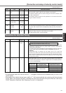
0E
*
0 to 1
<0>
Setup of front
panel lock
You can limit the operation of the front panel to the
monitor mode only.
You can prevent such a misoperation as unexpec-
ted parameter change.
<Note>
You can still change parameters via communication even though this setup is 1.
To return this parameter to 0, use the console or the "PANATERM
®
".
Setup value
<0>
1
Content
Valid to all
Monitor mode only
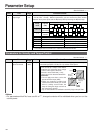
0D
*
0 to 5
<2>
Baud rate setup of
RS485
communication
You can set up the communication speed of RS485.
Setup value
0
1
<2>
Baud rate
2400bps
4800bps
9600bps
Setup value
3
4
5
Baud rate
19200bps
38400bps
57600bps
• Error of baud rate is ±0.5%.
PrNo.
Setup
range
Title Function/Content
Standard default : < >
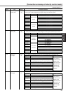
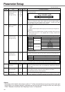
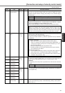
Parameters for Adjustment of Time Constants of Gains and Filters
Standard default : < >
PrNo.
Setup
range
UnitTitle Function/Content
11 1 to 3500
A to C-frame:<35>*
D to F-frame:<18>*
Hz1st gain of
velocity loop
You can determine the response of the velocity loop.
In order to increase the response of overall servo system by setting high
position loop gain, you need higher setup of this velocity loop gain as well.
However, too high setup may cause oscillation.
<Caution>
When the inertia ratio of Pr20 is set correctly, the setup unit of Pr11
becomes (Hz).
12 1 to 1000
A to C-frame:<16>*
D to F-frame:<31>*
ms1st time constant
of velocity loop
integration
You can set up the integration time constant of velocity loop.
Smaller the setup, faster you can dog-in deviation at stall to 0.
The integration will be maintained by setting to "999".
The integration effect will be lost by setting to "1000".
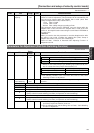
13 0 to 5
<0>*
–1st filter of
speed detection
You can set up the time constant of the low pass filter (LPF) after the
speed detection, in 6 steps.
Higher the setup, larger the time constant you can obtain so that you can
decrease the motor noise, however, response becomes slow. Use with a
default value of 0 in normal operation.
14 0 to 2500
A to C-frame:<65>*
D to F-frame:<126>*
0.01ms1st time constant of
torque filter
You can set up the time constant of the 1st delay filter inserted in the
torque command portion. You might expect suppression of oscillation
caused by distortion resonance.