


81
page
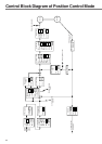
Control Block Diagram of Position Control Mode 82
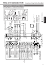
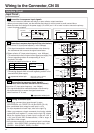
Wiring to the Connector, CN X5 .............................83
Wiring Example to the Connector, CN X5 ................................... 83
Interface Circuit ........................................................................... 84
Input Signal and Pin No. of the Connector, CN X5 ..................... 86
Output Signal and Pin No. of the Connector, CN X5 .................. 92
Connecting Example to Host Controller ...................................... 96
Trial Run (JOG Run) at Position Control Mode ..104
Inspection Before Trial Run ....................................................... 104
Trial Run by Connecting the Connector, CN X5........................ 104
Real-Time Auto-Gain Tuning ................................106
Outline ....................................................................................... 106
Applicable Range ...................................................................... 106
How to Operate ......................................................................... 106
Adaptive Filter ........................................................................... 107
Parameters Which are Automatically Set.................................. 107
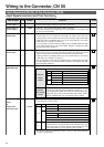
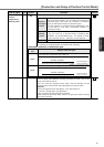
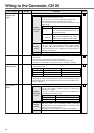
Parameter Setup....................................................108
Parameters for Functional Selection ......................................... 108
Parameters for Adjustment of Time Constant of Gains and Filters .......
111
Parameters for Auto-Gain Tuning...............................................112
Parameters for Adjustment (2nd Gain Switching Function) ....... 115
Parameters for Position Control .................................................116
Parameters for Velocity/Torque Control .................................... 120
Parameters for Sequence ......................................................... 120
[
Connection and Setup of Position Control Mode
]