


158
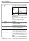
Parameter Setup
6C
*
0 to 3
for
A, B-frame
<3>
for
C to F-frame
<0>
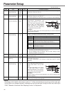
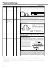
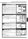
–Selection of
external
regenerative
resistor
With this parameter, you can select either to use the built-in regenerative
resistor of the driver, or to separate this built-in regenerative resistor and
externally install the regenerative resistor (between RB1 and RB2 of
Connector CN X2 in case of A to D-frame, between P and B2 of terminal
block in case of E, F-frame).
<Remarks>
Install an external protection such as thermal fuse when you use the
external regenerative resistor.
Otherwise, the regenerative resistor might be heated up abnormally and
result in burnout, regardless of validation or invalidation of regenerative
over-load protection.
<Caution>
When you use the built-in regenerative resistor, never to set up other
value than 0. Don't touch the external regenerative resistor.
External regenerative resistor gets very hot, and might cause burning.
Setup value
<0>
(C, D, E and
F-frame)
1
2
<3>
(A, B-frame)
Built-in resistor
External resistor
External resistor
No resistor
Regenerative processing circuit will be
activated and regenerative resistor overload
protection will be triggered according to the
built-in resistor (approx. 1% duty).
The driver trips due to regenerative overload
protection (Err18), when regenerative
processing circuit is activated and its active
ratio exceeds 10%,
Regenerative processing circuit is activated,
but no regenerative over-load protection is
triggered.
Both regenerative processing circuit and
regenerative protection are not activated, and
built-in capacitor handles all regenerative
power.
Regenerative resistor
to be used
Regenerative processing and
regenerative resistor overload
Standard default : < >
PrNo.
Setup
range
UnitTitle Function/Content
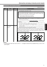
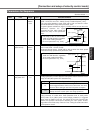
6D
*
35 to 1000
<35>
2msDetection time of
main power off
You can set up the time to detect the shutoff while the main power is kept
shut off continuously.
The main power off detection is invalid when you set up this to 1000.
6E 0 to 500
<0>
%Torque setup at
emergency stop
You can set up the torque limit in case of emergency stop as below.
• During deceleration of over-travel inhibit with the setup 2 of Pr66
(Sequence at over-travel inhibit input)
• During deceleration with the setup of 8 or 9 of Pr67 (Sequence at main
power off)
•
During deceleration with the setup of 8 or 9 of Pr69 (Sequence at Servo-OFF)
Normal torque limit is used by setting this to 0.
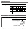
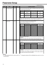
70
0 to 32767
<25000>
256 x
resolution
Setup of position
deviation excess
• You can set up the excess range of position deviation.
• Set up with the encoder pulse counts at the position control and with the
external scale pulse counts at the full-closed control.
• Err24 (Error detection of position deviation excess) becomes invalid
when you set up this to 0.
72 0 to 500
<0>
%Setup of
over-load level
• You can set up the over-load level. The overload level becomes 115 [%]
by setting up this to 0.
• Use this with 0 setup in normal operation. Set up other value only when
you need to lower the over-load level.
•
The setup value of this parameter is limited by 115[%] of the motor rating.
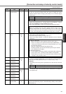
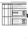
73
0 to 20000
<0>
r/minSetup of
over-speed level
• You can set up the over-speed level. The over-speed level becomes 1.2
times of the motor max. speed by setting up this to 0.
• Use this with 0 setup in normal operation. Set up other value only when
you need to lower the over-speed level.
• The setup value of this parameter is limited by 1.2 times of the motor
max. speed.
<Caution>
The detection error against the setup value is ±3 [r/min] in case of the 7-wire
absolute encoder, and ±36 [r/min] in case of the 5-wire incremental encoder.
<Notes>
•For parameters which No. have a suffix of "*", changed contents will be validated when you turn on the
control power.