


128
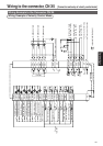
Wiring to the connector, CN X5
Interface Circuit
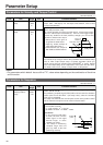
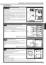
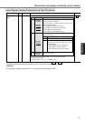
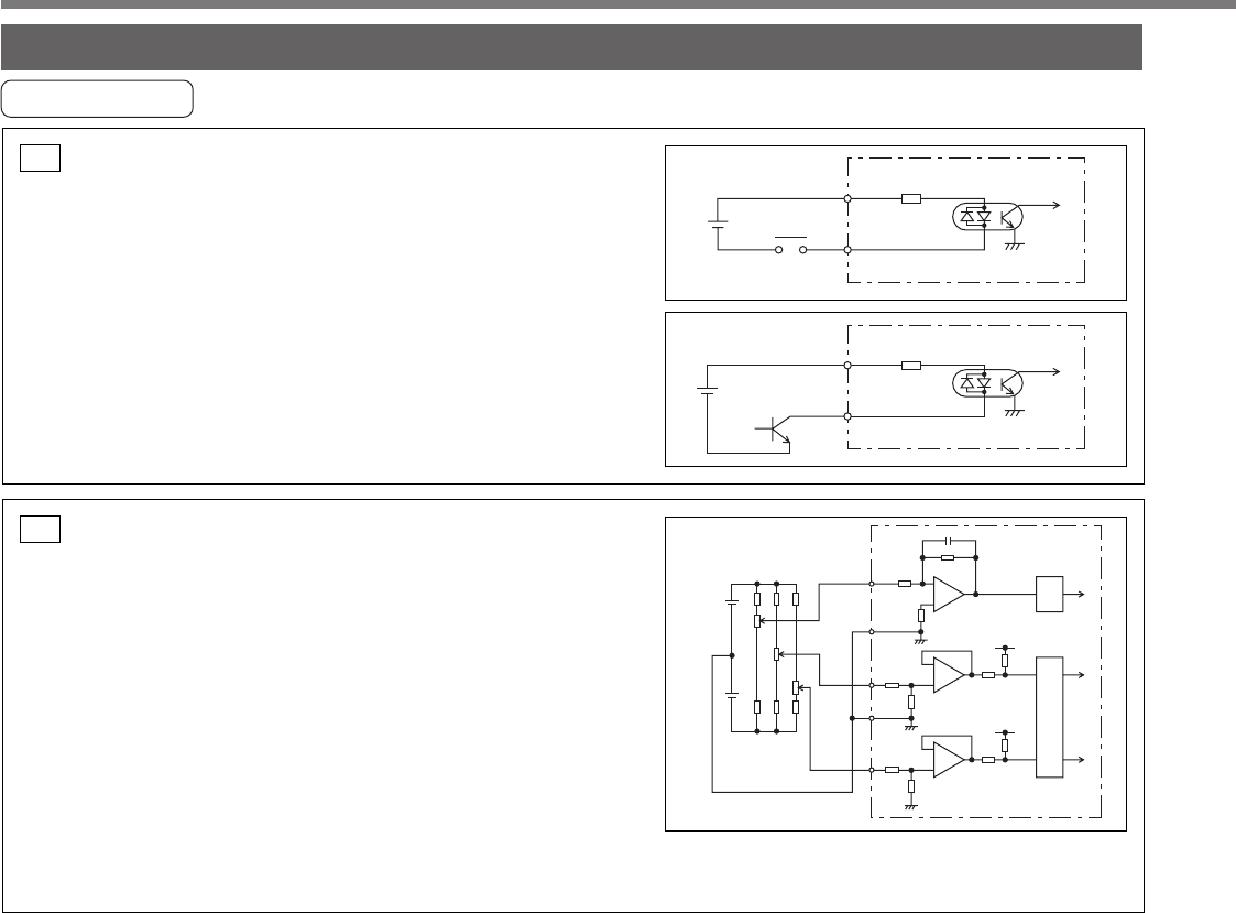
Input Circuit
• Connect to contacts of switches and relays, or open collector
output transistors.
• When you use contact inputs, use the switches and relays for
micro current to avoid contact failure.
• Make the lower limit voltage of the power supply (12 to 24V)
as 11.4V or more in order to secure the primary current for
photo-couplers.
Connection to sequence input signalsSI
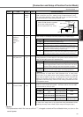
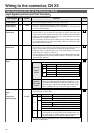
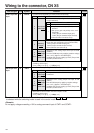
Analog command inputAI
• The analog command input goes through 3 routes,
SPR/TRQR(Pin-14), CCWTL (Pin-16) and CWTL (Pin-18).
• Max. permissible input voltage to each input is ±10V.
For input impedance of each input, refer to the right Fig.
• When you compose a simple command circuit using variable
resistor(VR) and register R, connect as the right Fig. shows.
When the variable range of each input is made as –10V to
+10V, use VR with 2kΩ, B-characteristics, 1/2W or larger, R
with 200Ω, 1/2W or larger.
• A/D converter resolution of each command input is as follows.
(1)ADC1 : 16 bit (SPR/TRQR), (including 1bit for sign), ±10V
(2)ADC2 : 10 bit (CCWTL, CWTL), 0 to 3.3V
+12V
+3.3V
SPR/TRQR
CCWTL
CWTL
R
14
20kΩ
20kΩ
1kΩ
1kΩ
10kΩ
GND
GND
10kΩ
3.83kΩ
3.83kΩ
ADC
1
ADC
2
15
16
17
18
R
VR
–12V
+
–
+
–
+
–
+3.3V
1kΩ
1kΩ
12 to 24V
7 COM+4.7kΩ
SRV-ON etc.
Relay
7 COM+4.7kΩ
12 to 24V
SRV-ON etc.