


35
[Preparation]
Preparation
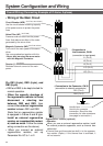
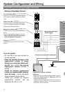
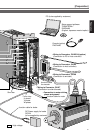
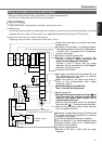
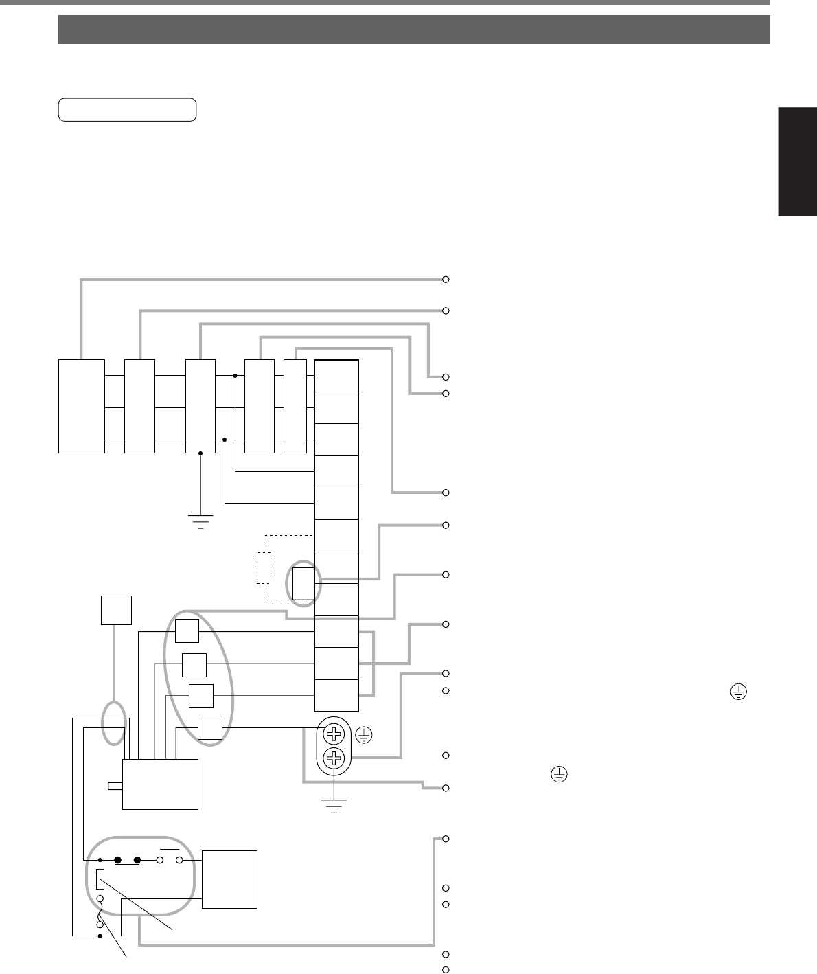
Wiring of the Main Circuit (E and F-frame)
• Wiring should be performed by a specialist or an authorized personnel.
• Do not turn on the power until the wiring is completed.
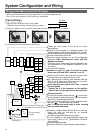
Tips on Wiring
1) Take off the cover fixing screws, and detach the terminal cover.
2) Make wiring
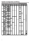
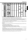
Use clamp type terminals of round shape with insulation cover for wiring to the terminal block. For cable
diameter and size, rater to "Driver and List of Applicable Peripheral Equipments" (P.32 and 33).
3) Attach the terminal cover, and fix with screws.
Fastening torque of cover fixed screw in less than 0.2 N
•
m.
Red
Black
Green/
Yellow
Motor
Surge absorber
DC
24V
White
NFB
Power
supply
DC power supply
for brake
NF MC
L1
U
V
W
E
L2
L3
r
t
P
B1
B2
U
V
W
L
Check the name plate of the driver for power
specifications.
Provide a circuit breaker, or a leakage breaker.
The leakage breaker to be the one designed for
"Inverter" and is equipped with countermea-
sures for harmonics.
Provide a noise filter without fail.
Provide a surge absorber to a coil of the
Magnetic Contactor. Never start/stop the
motor with this Magnetic Contactor.
Connect a fuse in series with the surge
absorber. Ask the manufacturer of the Magnetic
Contactor for the fuse rating.
Provide an AC Reactor.
Don't disconnect the short bar between B1 and
B2. Disconnect this only when an external
regenerative register is used.
Match the colors of the motor lead wires to
those of the corresponding motor output
terminals (U,V,W).
Avoid shorting and ground fault.
Don't connect the main power.
Earth-ground this.
Connect the protective earth terminal ( ) of
the driver and the protective earth (earth
plate) of the control panel without fail to
prevent electrical shock.
Don't co-clamp the earth wires to the protective
earth terminal ( ) . Two terminals are provided.
Don't connect the earth cable to other inserting
slot, nor make them touch.
Compose a duplex Brake Control Circuit so that
the brake can also be activated by an external
emergency stop signal.
The Electromagnetic Brake has no polarity.
For the capacity of the electromagnetic brake
and how to use it, refer to P.47, "Specifications
of Built-in Holding Brake".
Provide a surge absorber.
Connect a 5A fuse in series with the surge
absorber.
Yellow
(X2)
Ground resistance : 100Ω max.
For applicable wire, refer to P32 and 33.
Fuse (5A)