


242
Manual Gain Tuning (Basic)
Adjustment in Torque Control Mode
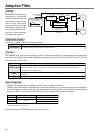
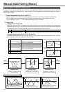
Torque control of MINAS-A4 series is described in P.160, "Block Diagram" of Torque Control Mode.
This torque control is based on velocity control while making the 4th speed of speed setup of Pr56 or SPR/
SPL input as a speed limit. Here we explain the setup of speed limiting value.
• Setup of speed limiting value
Setup the speed limiting value to the 4th speed of speed setup (Pr56) (when torque command
selection (Pr5B) is 0.) or to the analog speed command input (SPR/TRQR/SPL ) (when torque
command selection (Pr5B) is 1).
• When the motor speed approaches to the speed limiting value, torque control following the analog
torque command shifts to velocity control based on the speed limiting value which will be determined by
the 4th speed of speed setup (Pr56) or the analog speed command input (SPR/TRQR/SPL).
• In order to stabilize the movement under the speed limiting, you are required to set up the parameters
according to the above-mentioned "Adjustment in Velocity Control Mode".
• When the speed limiting value = 4th speed of speed setup (Pr56) , the analog speed command input is
too low or the velocity loop gain is too low, or when the time constant of the velocity loop integration is
1000 (invalid), the input to the torque limiting portion of the above fig. becomes small and the output
torque may not be generated as the analog torque command.
Adjustment in Full-Closed Control Mode
Full-closed control of MINAS-A4 series is described in Block diagram of P.191 of Full-Closed Control.
Adjustment in full-closed control is almost same as that in position control described in P.241 “Adjustment in
Position Control Mode”, and make adjustments of parameters per the procedures except cautions of P.190,
“Outline of Full-Closed Control” (difference of command unit, necessity of position loop unit conversion and
difference of electronic gear).
Here we explain the setup of external scale ratio, hybrid deviation excess and hybrid control at initial setup
of full-closed control.
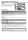
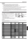
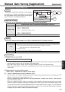
1) Setup of external scale ratio
Setup the external scale ratio using the numerator of external scale division (Pr78), the multiplier for
numerator of external scale division (Pr79) and denominator of external scale division (Pr7A).
• Check the encoder pulse counts per one motor revolution and the external scale pulse counts per one
motor revolution, then set up the numerator of external scale division (Pr78), the multiplier for numera-
tor of external scale division (Pr79) and denominator of external scale division so that the following
formula can be established.
• If this ratio is incorrect, a gap between the position calculated from the encoder pulse counts and that of
calculated from the external scale pulse counts will be enlarged and hybrid deviation excess (Err.25) will
be triggered when the work or load travels a long distance.
• When you set up Pr78 to 0, the encoder pulse counts will be automatically set up.
2) Setup of hybrid deviation excess
Set up the minimum value of hybrid deviation excess (Pt78) within the range where the gap between the
motor (encoder) position and the load (external scale) position will be considered to be an excess.
• Note that the hybrid deviation excess (Error code No.25) may be generated under other conditions than the
above 1), such as reversed connection of the external scale or loose connection of the motor and the load.
Pr78 1 x 2
Pr7A 5000
=
Pr79 17
Number of encoder pulses per motor rotation
Number of external scale pulses per motor rotation