


250
Damping Control
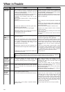
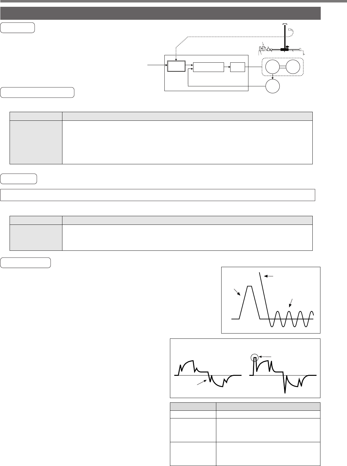
Outline
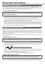
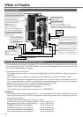
This function reduces the vibration by removing
the vibration frequency component from the
command when the load end of the machine
vibrates.
Applicable Range
This function can only be applicable when the following conditions are satisfied.
Caution
When you change the parameter setup or switch with VS-SEL, stop the action first then execute.
This function does not work properly or no effect is obtained under the following conditions.
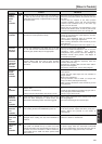
How to Use
(1) Setup of damping frequency (1st : Pr2B, 2nd : Pr2D))
Measure the vibration frequency of the front edge of the machine.
When you use such instrument as laser displacement meter, and can
directly measure the load end vibration, read out the vibration fre-
quency from the measured waveform and enter it to Pr2B or Pr2D
(Damping frequency).
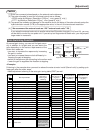
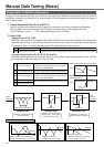
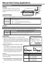
(2) Setup of damping filter (1st : Pr2C, 2nd : Pr2E))
First, set up 0.
You can reduce the settling time by setting up larger
value, however, the torque ripple increases at the
command changing point as the right fig. shows.
Setup within the range where no torque saturation
occurs under the actual condition. If torque satura-
tion occurs, damping control effect will be lost.
<Remark>
Limit the damping filter setup with the following formula.
10.0 [Hz] – Damping frequency
<
=
Damping filter setup
<
=
Damping frequency
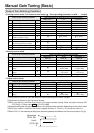
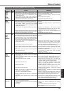
(3) Setup of damping filter switching selection (Pr24)
You can switch the 1st or the 2nd damping filter de-
pending on the vibration condition of the machine.
Control mode
Conditions under which the damping control is activated
• Control mode to be either or both position control or/and full-closed control.
Pr02 = 0 : Position control
Pr02 = 3 : 1st control mode of position and velocity control
Pr02 = 4 : 1st control mode of position control and torque control
Pr02 = 6 : Full-closed control
Command
speed
Position deviation
Calculation of
vibration frequency
Torque
command
Torque saturation
Damping filter setup is
too large.
Damping filter setup is
appropriate.
Switching mode
No switching ( Both of 2 are valid.)
Switch with VS-SEL input.
Open : 1st damping filter
Close : 2nd damping filter
Switch with command direction.
CCW : 1st damping filter
CW : 2nd damping filter
Pr24
0
1
2
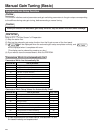
Servo driver
Motor position
Motor
Coupling
Ball
screw
Work
travel
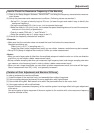
Driver
PLC
Setup of front edge vibration
frequency
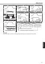
Motor
Encoder
Load
Position
command
Damping
filter
Position/Velocity
control
Torque
command
Current
control
Machine
base
Front edge vibrates.
Vibration
measurement
with
displacement
sensor
Motor
current
Load
Conditions which obstruct the damping control effect
• Vibration is triggered by other factors than command (such as disturbance).
• Ratio of resonance frequency and anti-resonance frequency is large.
• Vibration frequency is out of the range of 10.0-200.0 [Hz].
Manual Gain Tuning (Application)